
This blog post will walk you through a simple 8086 assembly program designed to add two 8-bit numbers. While seemingly basic, this example highlights fundamental concepts of assembly programming, register usage, and data manipulation. Let’s get started!
data segment
a db 09h
b db 02h
c dw ?
data ends

code segment
assume cs:code,ds:data
start:
mov ax,data
mov ds,ax
mov al,a
mov bl,b
add al,bl
mov c,ax
int 3
code ends
end start
Understanding the Code
The program is divided into a data segment and a code segment:
Data Segment:
- data segment: This section defines the variables.
- a db 09h: Declares an 8-bit byte variable a initialized to 09h (hexadecimal).
- b db 02h: Declares an 8-bit byte variable b initialized to 02h.
- c dw ?: Declares a 16-bit word variable c to store the sum. We use a 16-bit variable to handle potential overflow if the sum exceeds 255 (FFh).
Code Segment:
- code segment: This section contains the program instructions.
- assume cs:code,ds:data: Tells the assembler that the cs register points to the code segment and the ds register points to the data segment.
- start: The label marking the program’s entry point.
- mov ax,data: Loads the address of the data segment into the ax register.
- mov ds,ax: Sets the ds register to point to the data segment. This is crucial for accessing the variables a and b.
- mov al,a: Loads the value of a (09h) into the al register (the lower 8 bits of ax).
- mov bl,b: Loads the value of b (02h) into the bl register (the lower 8 bits of bx).
- add al,bl: Adds the contents of bl to al. The result (0Bh) is stored in al.
- mov c,ax: Moves the contents of ax (which now contains the sum in its lower byte, al) into the variable c.
- int 3: The breakpoint instruction halts execution for debugging purposes.
Flowchart
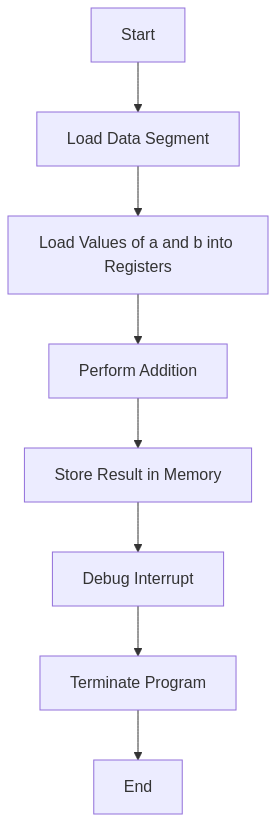
High-Level Overview
- Data Initialization: Variables a and b are initialized. Space is allocated for c.
- Segment Setup: The data segment is made accessible to the processor.
- Value Loading: The 8-bit values are loaded into the al and bl registers.
- Addition: The add instruction performs the 8-bit addition.
- Result Storage: The 16-bit sum (to accommodate potential overflow) is stored in c.
- Program Termination: The program halts.
Output
C:\TASM>masm an8add.asm
Microsoft (R) Macro Assembler Version 5.00
Copyright (C) Microsoft Corp 1981-1985, 1987.  All rights reserved.

Object filename [an8add.OBJ]:
Source listing  [NUL.LST]:
Cross-reference [NUL.CRF]:

  50402 + 450254 Bytes symbol space free

      0 Warning Errors
      0 Severe  Errors

C:\TASM>link an8add.obj

Microsoft (R) Overlay Linker  Version 3.60
Copyright (C) Microsoft Corp 1983-1987.  All rights reserved.

Run File [AN8ADD.EXE]:
List File [NUL.MAP]:
Libraries [.LIB]:
LINK : warning L4021: no stack segment

C:\TASM>debug an8add.exe
-g

AX=0B0B  BX=0002  CX=0022  DX=0000  SP=0000  BP=0000  SI=0000  DI=0000
DS=0B97  ES=0B87  SS=0B97  CS=0B98  IP=0011   NV UP EI PL NZ NA PO NC
0B98:0011 CC            INT     3
-d 0B97:0000
0B97:0000  09 02 0B 0B 00 00 00 00-00 00 00 00 00 00 00 00   ................
0B97:0010  B8 97 0B 8E D8 A0 00 00-8A 1E 01 00 02 C3 A3 02   ................
0B97:0020  00 CC 86 72 FF 77 15 8A-86 70 FF 2A E4 50 B8 FD   ...r.w...p.*.P..
0B97:0030  05 50 FF 36 24 21 E8 77-63 83 C4 06 FF 36 24 21   .P.6$!.wc....6$!
0B97:0040  B8 0A 00 50 E8 47 5E 83-C4 04 5E 8B E5 5D C3 90   ...P.G^...^..]..
0B97:0050  55 8B EC 81 EC 84 00 C4-5E 04 26 80 7F 0A 00 74   U.......^.&....t
0B97:0060  3E 8B 46 08 8B 56 0A 89-46 FC 89 56 FE C4 5E FC   >.F..V..F..V..^.
0B97:0070  26 8A 47 0C 2A E4 40 50-8B C3 05 0C 00 52 50 E8   &.G.*[email protected].
-q
Understanding the Memory Dump
This is the memory dump starting from address 0B97:0000, showing the contents of memory. Here is the breakdown:
0B97:0000 09 02 0B 0B 00 00 00 00-00 00 00 00 00 00 00 00 …………….
09:The valuea = 09h.02: The valueb = 02h.0B: The result of the addition0Bh, which is stored inc.
Adding 8-bit numbers in 8086 assembly is like using a tiny abacus 🧮 – simple in concept, yet foundational to more complex calculations 💡.
It will be if you will explian the program using comment lines…dont mind.
Added explanation