
Adding two 16-bit numbers is one of the first real programs every assembly language student writes — and for good reason. It touches every foundational concept at once: segment registers, data declarations, arithmetic instructions, result storage, and program termination. This post walks through a working implementation in three assembler environments: MASM/TASM (the classic DOS toolchain), emu8086 (the popular Windows emulator used in college labs), and NASM (the modern open-source assembler). All examples are tested and produce verifiable output.
Prerequisites: Basic familiarity with what a register is and how hexadecimal notation works. If you are new to 8086 assembly, read Understanding DW and DB in 8086 Assembly first.
The Problem: Adding 0202h and 0408h
We want to add two 16-bit values — 0202h and 0408h — and store the result in a third memory variable. The expected result is 060Ah (decimal 1546). The 8086 CPU has no single instruction that adds two memory operands directly; at least one operand must pass through a register. This constraint shapes the structure of every version below.
A quick sanity check before you even open the assembler: 0202h = 514 decimal, 0408h = 1032 decimal, and 514 + 1032 = 1546 = 060Ah. Always verify your expected output mentally first — it saves a lot of confused staring at the debugger later.
Version 1 — MASM / TASM (Classic DOS Toolchain)
This is the canonical 8086 addition program assembled with Microsoft MASM or Borland TASM on a real DOS machine (or DOSBox). The full session output — including the assembler, linker, and debugger — is shown in the Output section below.
; Data Segment

data segment
    a dw 0202h      ; 16-bit variable 'a' initialized with 0202h
    b dw 0408h      ; 16-bit variable 'b' initialized with 0408h
    c dw ?          ; 16-bit variable 'c' to store the result
data ends

; Code Segment

code segment
assume cs:code, ds:data
start:
    mov ax, data    ; Load the address of the data segment into AX
    mov ds, ax      ; Initialize the data segment register

    mov ax, a       ; Load value of 'a' into AX
    mov bx, b       ; Load value of 'b' into BX
    add ax, bx      ; Perform addition (AX = AX + BX)

    mov c, ax       ; Store the result in 'c'

    int 3           ; Halt program execution for debugging

code ends
end start           ; Mark the end of the program
16-bit addition in 8086: It’s like learning a new language, except the language is binary and the grammar is brutal 😉
Related Links:
Understanding the code:
Data Segment
- a dw 0202h: This line declares a 16-bit word variable named
aand initializes it with the hexadecimal value0202. - b dw 0408h: Similarly, this declares a 16-bit word variable
band initializes it with the hexadecimal value0408. - c dw ?: This declares a 16-bit word variable
cbut does not initialize it. It will store the result of the addition operation.
dw vs db: A very common beginner slip is writing db (define byte) instead of dw (define word) for 16-bit variables. db reserves only 1 byte (8 bits); loading a 16-bit value into it corrupts whatever sits next to it in memory. For 16-bit numbers, always use dw.
Code Segment
- mov ax,data: This instruction moves the address of the data segment into the
AXregister. - mov ds,ax: This sets the Data Segment (DS) register to the value in
AX, effectively making the data segment accessible for data operations. - mov ax,a: This moves the value of
a(0202h) into theAXregister. - mov bx,b: This moves the value of
b(0408h) into theBXregister. - add ax,bx: This adds the contents of
BXto the contents ofAX. The result (060Ah) is stored inAX. - mov c,ax: This moves the result from
AXto the variablec. - int 3: This is a breakpoint instruction that causes the program to halt, allowing for debugging and inspection of registers and memory.
int actually mean? INT stands for interrupt — it is a software instruction that hands control over to a specific interrupt handler. INT 3 triggers interrupt vector 3, which the debugger has set up as a breakpoint handler. INT 21h triggers DOS interrupt 33 (21 in hex), which provides DOS services like file I/O and program exit. They are completely different handlers; the number after int is just the interrupt vector index.
mov ax, data / mov ds, ax pair thinking it is boilerplate. It is not. Without it, DS still points to the PSP (Program Segment Prefix), not your data segment. Any subsequent memory access to a, b, or c will read garbage or crash. This two-line setup is mandatory in EXE programs.
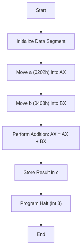
Flowchart
Overall Functionality
The code performs the following steps:
- Initialization: Sets up the data segment and initializes variables
aandb. - Addition: Loads the values of
aandbinto registersAXandBX, respectively. Adds the two values and stores the result inAX. - Result Storage: Stores the result from
AXinto the variablec. - Program Termination: Halts the program execution using the
int 3instruction.
In essence, this code adds two 16-bit hexadecimal numbers (0202h and 0408h) and stores the result (060Ah) in the variable c.
Output
C:TASM>masm an16add.asm
Microsoft (R) Macro Assembler Version 5.00
Copyright (C) Microsoft Corp 1981-1985, 1987.  All rights reserved.

Object filename [an16add.OBJ]:
Source listing  [NUL.LST]:
Cross-reference [NUL.CRF]:

  50402 + 450254 Bytes symbol space free

      0 Warning Errors
      0 Severe  Errors

C:TASM>link an16add.obj

Microsoft (R) Overlay Linker  Version 3.60
Copyright (C) Microsoft Corp 1983-1987.  All rights reserved.

Run File [AN16ADD.EXE]:
List File [NUL.MAP]:
Libraries [.LIB]:
LINK : warning L4021: no stack segment

C:TASM>debug an16add.exe
-g

AX=060A  BX=0408  CX=0022  DX=0000  SP=0000  BP=0000  SI=0000  DI=0000
DS=0B97  ES=0B87  SS=0B97  CS=0B98  IP=0011   NV UP EI PL NZ NA PE NC
0B98:0011 CC            INT     3
-d 0B97:0000
0B97:0000  02 02 08 04 0A 06 00 00-00 00 00 00 00 00 00 00   ................
0B97:0010  B8 97 0B 8E D8 A1 00 00-8B 1E 02 00 03 C3 A3 04   ................
0B97:0020  00 CC 86 72 FF 77 15 8A-86 70 FF 2A E4 50 B8 FD   ...r.w...p.*.P..
0B97:0030  05 50 FF 36 24 21 E8 77-63 83 C4 06 FF 36 24 21   .P.6$!.wc....6$!
0B97:0040  B8 0A 00 50 E8 47 5E 83-C4 04 5E 8B E5 5D C3 90   ...P.G^...^..].
0B97:0050  55 8B EC 81 EC 84 00 C4-5E 04 26 80 7F 0A 00 74   U.......^.&....t
0B97:0060  3E 8B 46 08 8B 56 0A 89-46 FC 89 56 FE C4 5E FC   >.F..V..F..V..^.
0B97:0070  26 8A 47 0C 2A E4 40 50-8B C3 05 0C 00 52 50 E8   &.G.*[email protected].
-q

C:TASM>
The key line to look for is AX=060A — that confirms the addition produced the correct result. BX=0408 shows the second operand is still intact in BX after the ADD, which is expected since ADD only modifies the destination register.
L4021: no stack segment is harmless for simple programs like this. It just means we did not declare a stack segment explicitly. DOS allocates a default stack, so the program runs fine. You can safely ignore this warning in lab assignments unless the program uses recursion or heavy procedure calls.
Understanding the Memory Dump
The memory dump provided by the -d 0B97:0000 command displays the contents of memory starting from the DS (data segment) base address, which is 0B97:0000 in this case.
Here is the relevant portion of the memory:
0B97:0000 02 02 08 04 0A 06 00 00-00 00 00 00 00 00 00 00
Here, 0A 06 is the result of a + b = 0202h + 0408h = 060Ah, stored in c. In the memory dump, values are stored in little-endian format, meaning the least significant byte appears first. Hence the result 060A is stored as 0A 06 in memory.
0A 06 in the memory dump and expect 060A, the instinct is to think the program is wrong. It is not. The 8086 always stores the low byte first. Read the two bytes in reverse order — 06 is the high byte, 0A is the low byte — and you get back 060Ah. Every x86 processor from the original 8086 to a modern Intel Core uses this same byte order.
Version 2 — emu8086 (Windows Emulator)
emu8086 is the assembler and emulator combination most commonly used in undergraduate computer organization labs. It accepts MASM-compatible syntax but provides a built-in IDE, step-by-step execution, and a register/memory viewer — making it ideal for learning. The program below uses emu8086’s #make_COM# directive to produce a simpler COM-format executable, which skips the separate linking step entirely.
Tested with: emu8086 v4.08 on Windows 10 (also works on Windows 11 via compatibility mode).
; emu8086 version -- 8086 Assembly Program to Add Two 16-bit Numbers
; Assemble as COM file using: #make_COM#

#make_COM#

org 100h            ; COM programs begin at offset 100h in memory

; --- Code ---
start:
    mov ax, a       ; Load first operand into AX
    mov bx, b       ; Load second operand into BX
    add ax, bx      ; AX = AX + BX  (result: 060Ah)
    mov c, ax       ; Store result into variable c

    ; Terminate program cleanly via DOS interrupt
    mov ax, 4c00h   ; AH = 4Ch (terminate), AL = 00h (exit code 0)
    int 21h         ; Call DOS to exit

; --- Data declarations ---
a dw 0202h          ; First operand: 0202h
b dw 0408h          ; Second operand: 0408h
c dw 0000h          ; Result variable, initialized to 0
int 21h alone without setting AH: INT 21h is a multi-function DOS interrupt. The value in AH selects which DOS service to call. If you write int 21h without first loading AH = 4Ch, DOS reads whatever junk happens to be in AH and calls a completely different function — sometimes printing garbage to the screen, sometimes doing nothing at all. The pattern mov ax, 4c00h sets both AH = 4Ch (exit) and AL = 00h (exit code) in one instruction.
How to Run in emu8086
- Open emu8086 and paste the code into the editor.
- Click Compile and Run (or press F5).
- After execution stops, open the Memory panel and navigate to the address of variable
c. You should see bytes0A 06— that is060Ahin little-endian order. - Alternatively, open the Registers panel immediately after the
addinstruction executes. TheAXregister will show060A.
Why no mov ax, data / mov ds, ax in this version? In a COM program, the entire file — code and data — loads into a single 64 KB segment. DOS sets all four segment registers (CS, DS, ES, SS) to the same value before handing control to offset 100h. Since DS already points to the correct segment, the data variables are immediately addressable without any extra setup.
Version 3 — NASM (Modern Open-Source Assembler)
NASM (Netwide Assembler) is the assembler of choice for systems programming, OS development, and competitive programming on Linux. Its syntax differs from MASM in one critical way: memory operands must be enclosed in square brackets. Writing mov ax, a in NASM moves the offset address of a into AX, not the value at that address. To dereference the pointer you must write mov ax, [a].
The version below targets a 16-bit DOS COM executable assembled with NASM on Linux (via DOSBox for execution) or on Windows with DOSBox-X.
Tested with: NASM 2.16.01, executed in DOSBox 0.74-3.
; NASM version -- 8086 Assembly Program to Add Two 16-bit Numbers
; Assemble:  nasm -f bin add16.asm -o add16.com
; Run:       Place add16.com in DOSBox and execute it

bits 16             ; Produce 16-bit machine code
org  100h           ; COM files load at offset 100h

; --- Code ---
start:
    mov ax, [a]     ; Load first operand from memory into AX  (0202h)
    mov bx, [b]     ; Load second operand from memory into BX (0408h)
    add ax, bx      ; AX = AX + BX  (result: 060Ah)
    mov [c], ax     ; Write result back to memory variable c

    ; Exit cleanly via DOS interrupt 21h, function 4Ch
    mov ax, 4c00h   ; AH = 4Ch (exit program), AL = 00h (return code)
    int 21h

; --- Data (placed after code in COM layout) ---
a dw 0202h          ; First 16-bit operand
b dw 0408h          ; Second 16-bit operand
c dw 0000h          ; Result storage
mov ax, a. In NASM that is legal — but it loads the address (offset) of a into AX, not the value stored there. Your program will assemble without errors, AX will contain some small offset number like 000Ch, and you will spend a long time wondering why the result is wrong. The fix is always mov ax, [a]. When in doubt in NASM, add the brackets.
Build and Run Steps
# Assemble to flat binary COM format
nasm -f bin add16.asm -o add16.com

# Verify the binary size (should be tiny -- about 14 bytes of code + 6 bytes of data)
ls -l add16.com

# Run inside DOSBox (mount current directory as C:)
# Inside DOSBox:
#   mount c .
#   c:
#   add16.com
Register State After Execution (All Three Versions)
Regardless of which assembler you use, the CPU register state after the add instruction is identical — because all three programs execute the same machine-code sequence on the same 8086-compatible processor model.
| Register | Value | Meaning |
|---|---|---|
| AX | 060A | Sum of 0202h + 0408h (the result) |
| BX | 0408 | Second operand — unchanged after ADD |
| CF (Carry Flag) | 0 | No carry — result fits in 16 bits |
| ZF (Zero Flag) | 0 | Result is not zero |
| SF (Sign Flag) | 0 | Result is positive |
| OF (Overflow Flag) | 0 | No signed overflow |
The Carry Flag is the one to watch in any addition program. Here it stays clear (0) because 060Ah is well within the 16-bit unsigned range (0 to FFFFh). This program does not check or handle carry — if you swap in two large values that sum beyond FFFFh, the result in c will silently wrap around and the carry will be lost. That is a separate problem handled in 8086 Assembly Program to Add Two 16-bit Numbers with Carry Handling.
Frequently Asked Questions
What exactly does int mean in int 3 and int 21h?
INT stands for interrupt. It is a CPU instruction that suspends the current program and jumps to a handler routine whose address is stored in the interrupt vector table — a lookup table at the very start of memory. The number after INT is just the index into that table. INT 3 jumps to vector 3, which debuggers like DOS DEBUG pre-configure as a breakpoint handler. INT 21h jumps to vector 33 (21 hex), which DOS sets up as its general-purpose service dispatcher — the function called depends on the value in AH when the interrupt fires. They have nothing in common beyond both being interrupt instructions.
Can I use .data instead of data segment … data ends?
It depends on the assembler. NASM uses section .data. In emu8086 and MASM, the simplified segment directive .data is supported as a shorthand — it is equivalent to data segment … data ends and automatically sets up the assume. However, the simplified form also requires .model small (or another memory model) at the top of the file, which the explicit segment form does not need. For lab assignments using the full segment syntax as shown in Version 1, stick with the explicit form to avoid confusion between the two styles.
What happens if I add two numbers whose sum exceeds FFFFh?
The 16-bit result wraps around (modulo 65536) and the Carry Flag (CF) is set to 1. For example, FFFFh + 0001h produces 0000h in AX with CF = 1. This program does not read CF after the addition, so the carry information is silently discarded and c will hold the wrapped-around value, not the true sum. If your operands might produce a sum larger than FFFFh, you need to check CF immediately after ADD and store it separately — typically using the ADC (add with carry) or JC (jump if carry) instruction. The full carry-handling version is covered at 8086 Assembly Program to Add Two 16-bit Numbers with Carry Handling.
Conclusion
Adding two 16-bit numbers in 8086 assembly is a three-step pattern you will use in almost every program you write: load operands into registers, perform the operation, store the result back to memory. That pattern does not change across MASM, emu8086, or NASM — only the syntactic details do. The mistakes that cost the most time are almost always the same ones: forgetting to initialize DS in EXE programs, misreading little-endian byte order in the memory dump, and dropping the brackets in NASM. Knowing those pitfalls going in puts you well ahead.
See Also
- Understanding DW and DB in 8086 Assembly — data declaration reference
- 8086 Assembly: Adding 16-bit Numbers with Carry Handling — extends this program to handle overflow
- 8086 Assembly Program to Add Two 16-bit Numbers — this post
What is dw and db in the programm
DW stands for define word. When we require 16 bit date, we use DW.
DB stands for define byte. When 8bit data is required, we use DW.
hi
db=define byte
dw=define word
These are assembler directives
dw = define word
db = define byte
used to specify the size of the data variable
Why have u took int 3
int 3 is used to terminate statements written above it.
thank you
WHAT IF CARRY GENERATED…..? THIS PROGRAM DOESNT HOLD GOOD FOR IT
Yes. That’s true. We have not handed carry in this program. Please refer following link for 8086 Assembly Program to Add Two 16-bit Numbers with Carry Handling.
https://ankurm.com/8086-assembly-program-to-add-two-16-bit-numbers-with-carry-handling/
int 21h is the last (isn’t it)
int 3 and int 21h both works fine, after all int 3 is used to terminate statements above it and int 21h is used to terminate whole program
What is int in int 3 and int 21h?
What is actually 16bit number?? What is history about it why 16bit no contain 4digits only
16=2^[4], hope you can understand further
can the [data segment] be defined as [.data]
this is done in NASM not TASM
db=define byte
dw=define word
Give the flowchart for program
Flowchart added for reference.
tthankss bhau
What is int in int 3 and int 21h?
bhot hard bhot hard
What is meant by int in int 3 and int 21h…
perfet website