
In this blog post, we will explore an 8086 assembly language program designed to convert a binary number into its Binary-Coded Decimal (BCD) format. This conversion is essential in applications where binary numbers need to be represented in a decimal-like format, such as digital displays or interfaces that require human-readable numbers.
The following assembly program performs the conversion:
DATA SEGMENT
NO1 DB "1001000000110110"
D1 DW 4 DUP (?)
DATA ENDS
CODE SEGMENT
ASSUME CS:CODE, DS:DATA
START:
MOV AX, DATA
MOV DS, AX
LEA SI, NO1
LEA DI, D1
MOV CX, 04H
TOP:
MOV BX, 00H
MOV AX, [SI]
ROR AX, 1
JNC P2
ADD BX, 08H
P2:
INC SI
MOV AX, [SI]
ROR AX, 1
JNC P3
ADD BX, 04H
P3:
INC SI
MOV AX, [SI]
ROR AX, 1
JNC P4
ADD BX, 02H
P4:
INC SI
MOV AX, [SI]
ROR AX, 1
JNC P5
ADD BX, 01H
P5:
MOV [DI], BX
INC DI
INC SI
DEC CX
JNZ TOP
INT 3
CODE ENDS
END START
Step-by-Step Explanation:
1. Data Segment:
NO1 DB "1001000000110110": Defines a string representing the binary number to be converted.D1 DW 4 DUP (?): Reserves space for four words to store the resulting BCD digits.
2. Code Segment:
MOV AX, DATAandMOV DS, AX: Initialize the data segment by loading its address into the AX register and then moving it to the DS register.LEA SI, NO1: Loads the effective address of the binary string into the SI register.LEA DI, D1: Loads the effective address of the destination array for BCD digits into the DI register.MOV CX, 04H: Sets the loop counter (CX) to 4, corresponding to the number of BCD digits to be processed.
3. Main Loop (TOP):
MOV BX, 00H: Initializes the BX register to 0; this will accumulate the value of each BCD digit.- Processing Each Bit:
- For each of the four bits in a BCD digit:
MOV AX, [SI]: Loads the current bit from the binary string into the AX register.ROR AX, 1: Rotates the bits of AX to the right by one position; the least significant bit (LSB) moves to the carry flag (CF).JNC Pn: If the CF is not set (indicating the bit was ‘0’), jump to the next processing label.ADD BX, value: If the CF is set (indicating the bit was ‘1’), add the corresponding decimal value to BX (8, 4, 2, or 1).Pn:: Label for each bit processing step.INC SI: Move to the next bit in the binary string.
- For each of the four bits in a BCD digit:
- After processing all four bits of a BCD digit:
MOV [DI], BX: Stores the accumulated BCD digit into the destination array.INC DI: Moves to the next position in the destination array.DEC CX: Decrements the loop counter.JNZ TOP: If CX is not zero, repeat the loop for the next BCD digit.
4. Program Termination:
INT 3: Generates a breakpoint interrupt to terminate the program execution.
Flowchart:
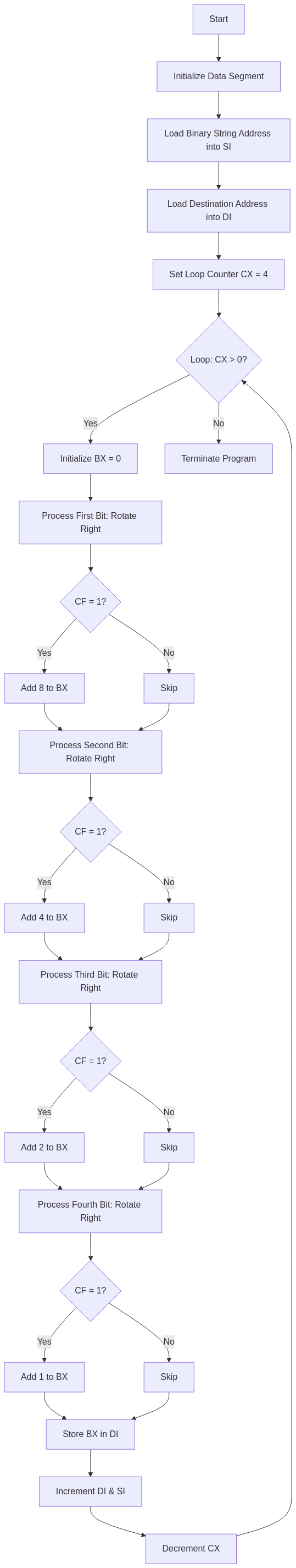
Overall Process:
- The program initializes registers and sets up pointers to the binary string and the destination array.
- It processes each group of four bits (nibble) from the binary string to convert them into their corresponding BCD digits.
- For each bit in the nibble, it checks if the bit is ‘1’ and adds the appropriate decimal value to the BX register.
- After processing four bits, it stores the resulting BCD digit into the destination array.
- This process repeats for all nibbles in the binary string.
- The program terminates after all BCD digits are processed.
Output
C:\TASM>MASM binbcd.asm
Microsoft (R) Macro Assembler Version 5.00
Copyright (C) Microsoft Corp 1981-1985, 1987. All rights reserved.
Object filename [binbcd.OBJ]:
Source listing [NUL.LST]:
Cross-reference [NUL.CRF]:
50324 + 450332 Bytes symbol space free
0 Warning Errors
0 Severe Errors
C:\TASM>LINK BINBCD.OBJ
Microsoft (R) Overlay Linker Version 3.60
Copyright (C) Microsoft Corp 1983-1987. All rights reserved.
Run File [BINBCD.EXE]:
List File [NUL.MAP]:
Libraries [.LIB]:
LINK : warning L4021: no stack segment
C:\TASM>DEBUG BINBCD.EXE
-G
AX=0498 BX=0006 CX=0000 DX=0000 SP=0000 BP=0000 SI=0010 DI=0014
DS=0B97 ES=0B87 SS=0B97 CS=0B99 IP=0041 NV UP EI PL ZR NA PE NC
0B99:0041 CC INT 3
-D 0B97:0000
0B97:0000 31 30 30 31 30 30 30 30-30 30 31 31 30 31 31 30 1001000000110110
0B97:0010 09 00 03 06 00 00 00 00-00 00 00 00 00 00 00 00 ................
0B97:0020 B8 97 0B 8E D8 8D 36 00-00 8D 3E 10 00 B9 04 00 ......6...>.....
0B97:0030 BB 00 00 8B 04 D1 C8 73-03 83 C3 08 46 8B 04 D1 .......s....F...
0B97:0040 C8 73 03 83 C3 04 46 8B-04 D1 C8 73 03 83 C3 02 .s....F....s....
0B97:0050 46 8B 04 D1 C8 73 03 83-C3 01 89 1D 47 46 49 75 F....s......GFIu
0B97:0060 CF CC 46 08 8B 56 0A 89-46 FC 89 56 FE C4 5E FC ..F..V..F..V..^.
0B97:0070 26 8A 47 0C 2A E4 40 50-8B C3 05 0C 00 52 50 E8 &.G.*[email protected].
-Q
Understanding the Memory Dump
The memory dump displayed in the DEBUG session shows the contents of memory after running the program. Let’s analyze the key parts.
| Memory Address | Value (Hex) | Binary Representation | Decimal Equivalent (BCD Digit) | Explanation |
|---|---|---|---|---|
0B97:0000 to 0B97:000F | 31 30 30 31 30 30 30 30 30 30 31 31 30 31 31 30 | 1001000000110110 (Original binary string) | N/A | The input binary string stored in memory |
0B97:0010 | 09 | 0000 1001 | 9 | First BCD digit (converted from binary 1001) |
0B97:0011 | 00 | 0000 0000 | 0 | Second BCD digit (converted from binary 0000) |
0B97:0012 | 03 | 0000 0011 | 3 | Third BCD digit (converted from binary 0011) |
0B97:0013 | 06 | 0000 0110 | 6 | Fourth BCD digit (converted from binary 0110) |
Summary of Output:
- The original binary number 1001000000110110 is processed in groups of 4 bits each.
- Each 4-bit group is converted into its BCD representation.
- The final BCD output is stored in memory at
0B97:0010to0B97:0013. - The final BCD result is
09 00 03 06, which corresponds to the decimal representation9 0 3 6.