
In this blog post, we’ll explore how to count the number of ‘0’s and ‘1’s in a binary string using an 8086 assembly language program. The following code snippet demonstrates this process:
DATA SEGMENT
STR1 DB "00011100"
NZ DW ?
NO DW ?
DATA ENDS
CODE SEGMENT
ASSUME CS:CODE, DS:DATA
START:
MOV AX, DATA
MOV DS, AX
LEA SI, STR1
MOV BX, 00H
MOV DX, 00H
MOV CX, 08H
UP:
MOV AX, [SI]
ROR AX, 1
JNC ZE
INC BX
JMP DN
ZE:
INC DX
DN:
INC SI
DEC CX
JNZ UP
MOV NZ, DX
MOV NO, BX
INT 3
CODE ENDS
END START
Step-by-Step Explanation:
1. Data Segment:
STR1: Defines a string of binary characters: “00011100”.NZ: Reserves a word (16 bits) to store the count of ‘0’s.NO: Reserves a word to store the count of ‘1’s.
2. Code Segment:
Initialization:
MOV AX, DATA: Loads the address of the data segment into the AX register.MOV DS, AX: Sets the DS register to point to the data segment, allowing access to variables.LEA SI, STR1: Loads the address of the first character of theSTR1string into the SI register.MOV BX, 00H: Initializes the BX register to 0; this will count the number of ‘1’s.MOV DX, 00H: Initializes the DX register to 0; this will count the number of ‘0’s.MOV CX, 08H: Sets the loop counter CX to 8, corresponding to the length of the string.
Loop to Count ‘0’s and ‘1’s:
MOV AX, [SI]: Loads the current character from the string into the AX register.ROR AX, 1: Rotates the bits of AX to the right by one position; the least significant bit (LSB) moves to the carry flag (CF).JNC ZE: If the CF is not set (indicating the bit was ‘0’), jump to theZElabel.INC BX: If the CF is set (indicating the bit was ‘1’), increment the BX register (count of ‘1’s).JMP DN: Jump to theDNlabel to continue.ZE:: Label reached when the bit is ‘0’.INC DX: Increment the DX register (count of ‘0’s).DN:: Label to continue the loop.INC SI: Move to the next character in the string.DEC CX: Decrement the loop counter.JNZ UP: If CX is not zero, repeat the loop.
Storing the Result:
MOV NZ, DX: Stores the count of ‘0’s (in DX) into theNZvariable.MOV NO, BX: Stores the count of ‘1’s (in BX) into theNOvariable.
Program Termination:
INT 3: Generates an interrupt 3, which typically halts the program execution.
Flowchart:
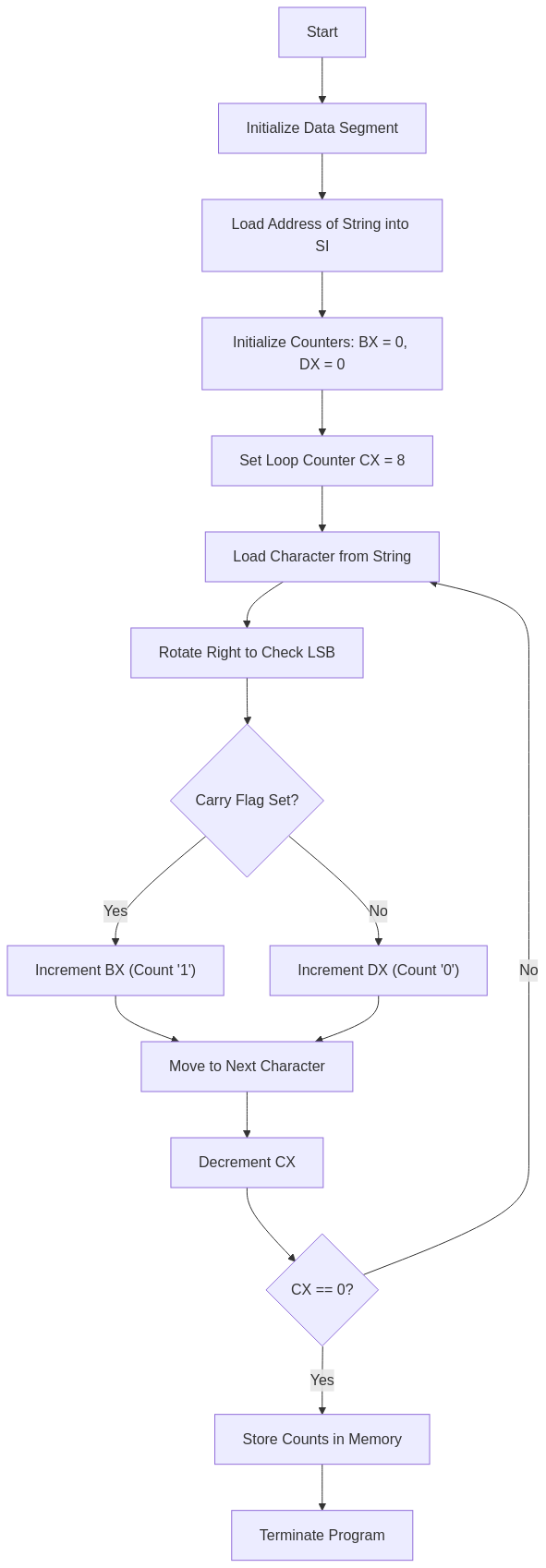
Overall Process:
- The program initializes registers and sets up pointers to the string.
- It iterates through each character in the string.
- For each character, it rotates the bits to check the LSB and updates the count of ‘0’s or ‘1’s accordingly.
- After processing all characters, the counts are stored in the
NZandNOvariables. - The program terminates.
Output
C:\TASM>MASM CZO.ASM
Microsoft (R) Macro Assembler Version 5.00
Copyright (C) Microsoft Corp 1981-1985, 1987. All rights reserved.
Object filename [CZO.OBJ]:
Source listing [NUL.LST]:
Cross-reference [NUL.CRF]:
50346 + 450310 Bytes symbol space free
0 Warning Errors
0 Severe Errors
C:\TASM>LINK CZO.OBJ
Microsoft (R) Overlay Linker Version 3.60
Copyright (C) Microsoft Corp 1983-1987. All rights reserved.
Run File [CZO.EXE]:
List File [NUL.MAP]:
Libraries [.LIB]:
LINK : warning L4021: no stack segment
C:\TASM>DEBUG CZO.EXE
-G
AX=0018 BX=0003 CX=0000 DX=0005 SP=0000 BP=0000 SI=0008 DI=0000
DS=0B97 ES=0B87 SS=0B97 CS=0B98 IP=0029 NV UP EI PL ZR NA PE NC
0B98:0029 CC INT 3
-D 0B97:0000
0B97:0000 30 30 30 31 31 31 30 30-05 00 03 00 00 00 00 00 00011100........
0B97:0010 B8 97 0B 8E D8 8D 36 00-00 BB 00 00 BA 00 00 B9 ......6.........
0B97:0020 08 00 8B 04 D1 C8 73 04-43 EB 02 90 42 46 49 75 ......s.C...BFIu
0B97:0030 F1 89 16 08 00 89 1E 0A-00 CC C4 06 FF 36 24 21 .............6$!
0B97:0040 B8 0A 00 50 E8 47 5E 83-C4 04 5E 8B E5 5D C3 90 ...P.G^...^..]..
0B97:0050 55 8B EC 81 EC 84 00 C4-5E 04 26 80 7F 0A 00 74 U.......^.&....t
0B97:0060 3E 8B 46 08 8B 56 0A 89-46 FC 89 56 FE C4 5E FC >.F..V..F..V..^.
0B97:0070 26 8A 47 0C 2A E4 40 50-8B C3 05 0C 00 52 50 E8 &.G.*[email protected].
-Q
Understanding the Memory Dump
The memory dump displayed in the DEBUG session shows the contents of memory after running the program. Let’s analyze the key parts.
Memory Dump Output:
-D 0B97:0000
0B97:0000 30 30 30 31 31 31 30 30-05 00 03 00 00 00 00 00 00011100........
Summary of the Memory Dump Analysis:
| Address Range | Content | Description |
|---|---|---|
0B97:0000 – 0B97:0007 | 30 30 30 31 31 31 30 30 | Binary string "00011100" in ASCII |
0B97:0008 – 0B97:0009 | 05 00 | Count of '0' (NZ = 5) |
0B97:000A – 0B97:000B | 03 00 | Count of '1' (NO = 3) |
0B97:000C – 0B97:000F | 00 00 00 00 | Unused/garbage data |
This confirms that the program correctly counted the number of ‘0’s and ‘1’s and stored them in memory.