
The first assembly exercise most students write touches four registers: AX, CX, DX, and BX, usually in that order. By the second week, they’ve discovered that two of those registers have hidden obligations — MUL silently writes into DX, LOOP quietly owns CX — and the bugs that follow take an hour to diagnose. I wrote this reference after going through exactly that experience in a microprocessor architecture course in my third year, and again later when I was building a small 8086 emulator in C and needed a reliable answer to “which registers are valid inside an effective address?” — because getting that wrong produces an assembler error with no intuitive explanation.
The Intel 8086 has exactly 14 programmer-visible registers, each with a fixed width and — in many cases — aliases for 8-bit access. This reference was built from the Intel 8086 Microprocessor Datasheet (order number 231455), the 8086 Family User’s Manual (1979), and hands-on testing in DOSBox-X and EMU8086. Where behaviour differs between emulators and real hardware (FLAGS edge cases, segment override interactions), I’ve noted it explicitly.
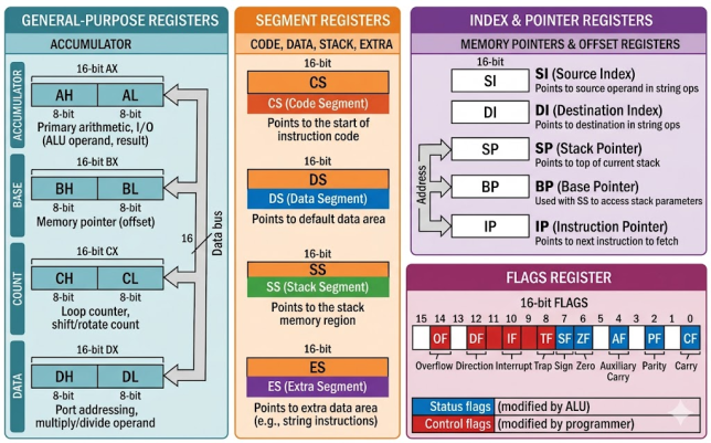
Master Quick-Reference: All 14 Registers at a Glance
| Register | Size | Type | Sub-registers / Aliases | Primary Purpose | Key Instructions |
|---|---|---|---|---|---|
| AX | 16-bit | General-purpose | AH (bits 15–8), AL (bits 7–0) | Accumulator — arithmetic, I/O, multiply/divide results | ADD, MUL, DIV, IN, OUT |
| BX | 16-bit | General-purpose | BH (bits 15–8), BL (bits 7–0) | Base register — memory base addressing | MOV AX,[BX] · MOV AX,[BX+SI] |
| CX | 16-bit | General-purpose | CH (bits 15–8), CL (bits 7–0) | Counter — loop count, shift/rotate count, REP prefix | LOOP, SHL, SHR, REP MOVSB |
| DX | 16-bit | General-purpose | DH (bits 15–8), DL (bits 7–0) | Data — I/O port address, extended multiply/divide | MUL, DIV, IN, OUT, CWD |
| CS | 16-bit | Segment | — | Code Segment — base of currently executing code | (implicit in every instruction fetch) |
| DS | 16-bit | Segment | — | Data Segment — default base for most data references | MOV, CMP, most data instructions |
| SS | 16-bit | Segment | — | Stack Segment — base of the stack | PUSH, POP, CALL, RET |
| ES | 16-bit | Segment | — | Extra Segment — destination for string operations | MOVS, STOS, CMPS, SCAS |
| SI | 16-bit | Index | — | Source Index — source pointer for string operations | MOVS, LODS, CMPS |
| DI | 16-bit | Index | — | Destination Index — destination pointer for string ops | MOVS, STOS, SCAS |
| SP | 16-bit | Pointer | — | Stack Pointer — offset of top-of-stack within SS | PUSH, POP, CALL, RET |
| BP | 16-bit | Pointer | — | Base Pointer — stack-frame access in procedures | MOV AX,[BP+4] |
| IP | 16-bit | Pointer | — | Instruction Pointer — offset of next instruction within CS | (implicit; modified by JMP, CALL, RET, INT) |
| FLAGS | 16-bit | Status/Control | CF, PF, AF, ZF, SF, TF, IF, DF, OF | Condition codes and CPU control flags | Jcc, CLC, STC, CLI, STI, CLD, STD |
General-Purpose Registers: AX, BX, CX, DX
The four general-purpose registers are the workhorse registers of 8086 assembly. Each is 16 bits wide and can be split into two independent 8-bit sub-registers — the high byte and the low byte. Although they are labelled “general-purpose,” each has strongly preferred roles that specific instructions enforce by design.
AX — The Accumulator Register
| Attribute | Value |
|---|---|
| Full name | Accumulator Register |
| Width | 16-bit (AX) · 8-bit halves: AH (high byte), AL (low byte) |
| Preferred role | Arithmetic results, I/O data, multiply/divide operand and result |
| Mandatory role | MUL/IMUL — 32-bit result in DX:AX; DIV/IDIV — dividend in DX:AX; IN/OUT — data register |
| Typical instructions | ADD AX,BX · MUL BX · DIV CX · IN AL,60h · OUT 60h,AL · XCHG AX,BX · CBW · DAA |
How it splits: AX = (AH << 8) | AL. Writing to AH or AL independently does not disturb the other half, which is useful when you need two independent 8-bit values (e.g., a character and a flag) without consuming a second 16-bit register.
; AX as accumulator: add two numbers
MOV AX, 0005h       ; AX = 5
ADD AX, 0003h       ; AX = 8  (result stays in AX)
; AX in 16-bit multiplication
MOV AX, 000Ah       ; AX = 10  (multiplicand)
MOV BX, 0003h       ; BX = 3   (multiplier)
MUL BX              ; DX:AX = 10 * 3 = 30 → DX = 0000h, AX = 001Eh
; AX for I/O: read a byte from keyboard data port
IN  AL, 60h         ; AL ← byte from port 60h
Pitfall: After MUL BX, the full 32-bit result is in DX:AX. Beginners often ignore DX and get silent overflow bugs when the product exceeds 0xFFFF. Always check DX after multiplication. See a complete example in the 8086 Assembly Simple Calculator.
BX — The Base Register
| Attribute | Value |
|---|---|
| Full name | Base Register |
| Width | 16-bit (BX) · 8-bit halves: BH (high byte), BL (low byte) |
| Preferred role | Memory base address in indirect and indexed addressing modes |
| Addressing modes supported | [BX] · [BX+SI] · [BX+DI] · [BX+disp] · [BX+SI+disp] |
| Typical instructions | MOV AX,[BX] · MOV [BX+SI],AL · LEA BX,array · XLAT |
BX is the only general-purpose register that can serve as a memory base inside an effective address. This makes it essential for traversing arrays, implementing lookup tables, and passing pointers between procedures. The XLAT instruction implicitly uses BX as a table-base pointer with AL as the index — it replaces AL with [BX + AL] in a single cycle.
; BX as base register for array traversal
MOV BX, OFFSET array  ; BX → start of array
MOV SI, 0             ; SI = element index
MOV AL, [BX + SI]     ; AL = array[0]
INC SI
MOV AL, [BX + SI]     ; AL = array[1]
; XLAT: single-instruction table lookup
MOV BX, OFFSET table  ; BX = base of translation table
MOV AL, 05h           ; AL = index
XLAT                  ; AL = table[5]
BX serves as the array base in both the Find Largest Number and the Sieve of Eratosthenes programs.
CX — The Counter Register
| Attribute | Value |
|---|---|
| Full name | Counter Register |
| Width | 16-bit (CX) · 8-bit halves: CH (high byte), CL (low byte) |
| Preferred role | Loop counter; shift/rotate count; REP prefix iteration count |
| Mandatory role | LOOP decrements CX and jumps if CX ≠ 0; SHL/SHR/ROL/ROR with variable count use CL exclusively; REP/REPE/REPNE use CX |
| Typical instructions | LOOP · SHL AX,CL · SHR BX,CL · ROL DX,CL · REP MOVSB · JCXZ |
; CX as loop counter — sum a word array of 5 elements
MOV CX, 5              ; loop 5 times
MOV BX, OFFSET array   ; BX → array start
MOV AX, 0              ; AX = running sum
sum_loop:
  ADD AX, [BX]         ; AX += current word
  ADD BX, 2            ; advance pointer (word = 2 bytes)
  LOOP sum_loop        ; CX--, jump back if CX != 0
; CL as shift count — multiply AX by 8 (left-shift by 3)
MOV CL, 3
SHL AX, CL             ; AX = AX * 8
; JCXZ — skip the loop entirely if CX starts at 0
JCXZ done
Pitfall: If CX equals 0 when LOOP executes, it decrements CX to 0xFFFF (65535) and runs 65,536 iterations before the loop ends. Always initialise CX explicitly before the loop. CX drives the loops in the Factorial Using Loops, Fibonacci Sequence, and Count 0s and 1s programs.
DX — The Data Register
| Attribute | Value |
|---|---|
| Full name | Data Register |
| Width | 16-bit (DX) · 8-bit halves: DH (high byte), DL (low byte) |
| Preferred role | High word of 32-bit multiply/divide; I/O port address for ports above 0xFF |
| Mandatory role | MUL/IMUL: high 16 bits of result in DX; DIV/IDIV: high 16 bits of dividend in DX; IN/OUT with port > 255: port address must be in DX |
| Typical instructions | MUL BX (DX:AX = result) · DIV CX · IN AX,DX · OUT DX,AX · CWD |
; DX holds the high word after 16x16 multiplication
MOV AX, 1000h          ; AX = 0x1000 (multiplicand)
MOV BX, 0010h          ; BX = 0x0010 (multiplier)
MUL BX                 ; DX:AX = 0x10000 → DX = 0x0001, AX = 0x0000
; DX as I/O port address (port value > 255)
MOV DX, 0378h          ; parallel port base address
IN  AL, DX             ; AL = byte from port 0x378
OUT DX, AL             ; write byte back to port 0x378
; CWD: sign-extend AX into DX for signed division (IDIV)
MOV AX, 0FFFEh         ; AX = -2 in two's complement
CWD                    ; DX = 0xFFFF (sign extension of AX)
; DX:AX now = -2 as 32-bit signed, ready for IDIVThese four registers look identical but have asymmetric mandatory roles. BX is the only GPR usable as a memory base in an effective address — [AX] or [CX] is an assembler error. CL is the only register accepted as a variable shift count by SHL/SHR/ROL/ROR. MUL always writes into DX:AX regardless of what DX holds — the most common source of silent register corruption. Before using any of these four in a loop, verify you haven’t put something in their mandatory slot that MUL, LOOP, or a shift will silently overwrite.
Segment Registers: CS, DS, SS, ES
The 8086 uses a segmented memory model. Every memory access combines a 16-bit segment register with a 16-bit offset register to produce a 20-bit physical address:
; Physical Address formula:
;   Physical Address = (Segment Register * 16) + Offset
;
; Multiplying by 16 is equivalent to shifting left by 4 bits,
; which extends a 16-bit segment value to a 20-bit base address.
; This gives the 8086 access to 2^20 = 1,048,576 bytes (1 MB).
;
; Example: DS = 1000h, BX = 0250h
;   Physical = (0x1000 * 16) + 0x0250 = 0x10000 + 0x0250 = 0x10250
For the full explanation of segment arithmetic and overlapping windows, see Introduction to Memory Segmentation in 8086.
| Register | Full Name | Default Offset Pairing | Can Be Changed? | Purpose |
|---|---|---|---|---|
| CS | Code Segment | IP | No (only via far JMP / CALL / RET / INT / IRET) | Defines where executable code lives |
| DS | Data Segment | BX, SI, DI (most data accesses) | Yes — segment override prefix (ES:, SS:, CS:) | Default base for most data operands |
| SS | Stack Segment | SP and BP | Yes (but dangerous in production code) | Defines the stack region |
| ES | Extra Segment | DI (destination in string ops) | Yes | Destination segment for MOVS, STOS, CMPS, SCAS |
CS — Code Segment
CS holds the segment address of the currently executing code. The CPU fetches every instruction from physical address (CS × 16) + IP. You cannot load CS with a plain MOV; it changes only via far jumps (JMP FAR), far calls (CALL FAR), far returns (RETF), and software or hardware interrupts with their matching IRET. In MASM programs using .MODEL SMALL, the loader sets CS automatically before transferring control to start.
DS — Data Segment
DS is the default segment for all memory operands that use BX, SI, or DI as an offset. The instruction MOV AX, [BX] reads from physical address (DS × 16) + BX. In MASM programs, DS must be explicitly loaded at startup because the CPU does not automatically point DS at the data segment:
; Standard DS initialisation — required at the top of every .COM/.EXE
MOV AX, @data       ; AX = paragraph address of the data segment
MOV DS, AX          ; DS = AX  (cannot MOV DS directly from immediate)
You can override DS for a single instruction using a segment override prefix: MOV AX, ES:[BX] reads from ES instead of DS. This pattern appears in every program on this site — see 8086 MASM Addition of Two 8-bit Numbers for the canonical setup sequence.
SS — Stack Segment
SS holds the segment address of the stack. Together with SP, the physical top-of-stack is always at (SS × 16) + SP. The PUSH, POP, CALL, and RET instructions use SS:SP implicitly. BP also defaults to SS when used as a base in memory operands — the instruction MOV AX, [BP+4] reads from (SS × 16) + BP + 4, which is how stack-frame parameters are accessed inside procedures. See the full mechanics in 8086 Stack Operations: SS:SP, PUSH/POP, CALL/RET, and Stack Frames.
ES — Extra Segment
ES is the dedicated destination segment for the 8086 string instructions. When MOVSB executes, the source byte is read from DS:SI and written to ES:DI. Setting ES equal to DS (as most single-segment programs do) means source and destination share the same segment, covering the common case. When copying data between two distinct memory regions, you set ES to a different value.
; Copy 10 bytes from src to dst within the same segment
MOV AX, @data
MOV DS, AX
MOV ES, AX              ; ES = DS  (same segment — common pattern)
MOV SI, OFFSET src      ; DS:SI = source address
MOV DI, OFFSET dst      ; ES:DI = destination address
MOV CX, 10              ; repeat 10 times
CLD                     ; DF = 0  (auto-increment SI and DI)
REP MOVSB               ; copy while CX > 0; SI++, DI++, CX-- each iteration
Index and Pointer Registers: SI, DI, SP, BP, IP
These five registers all hold 16-bit offsets. Unlike the general-purpose registers, they are never split into 8-bit halves. Each is tightly coupled to a specific segment register and a specific class of operations.
SI — Source Index Register
| Attribute | Value |
|---|---|
| Default segment pairing | DS (can be overridden with ES:, SS:, CS:) |
| Primary role | Source address for string operations; general-purpose index in memory addressing |
| Auto-adjust behaviour | MOVSB/MOVSW, LODSB/LODSW, CMPSB/CMPSW adjust SI by 1 or 2 depending on DF (0 = increment, 1 = decrement) |
| Addressing modes | [SI] · [BX+SI] · [BP+SI] · [SI+disp] |
; LODSB loads byte at DS:SI into AL, then adjusts SI
MOV SI, OFFSET message  ; SI → first character
CLD                     ; DF = 0, SI increments after each load
LODSB                   ; AL = message[0], SI++
LODSB                   ; AL = message[1], SI++
DI — Destination Index Register
| Attribute | Value |
|---|---|
| Default segment pairing | ES (cannot be overridden for the destination of string instructions) |
| Primary role | Destination address for string operations; general-purpose index |
| Auto-adjust behaviour | MOVSB/MOVSW, STOSB/STOSW, CMPSB/CMPSW, SCASB/SCASW adjust DI by 1 or 2 |
| Addressing modes | [DI] · [BX+DI] · [BP+DI] · [DI+disp] |
Key rule: DI always uses ES as its segment for string instruction destinations, regardless of any segment override prefix on the instruction. This is why string-copy code always initialises both DS and ES before executing REP MOVSB. SI and DI pair together in the Sort Numbers in Ascending Order and Sort Numbers in Descending Order programs.
SP — Stack Pointer
| Attribute | Value |
|---|---|
| Default segment pairing | SS (Stack Segment) |
| Primary role | Always holds the offset of the current top-of-stack within SS |
| PUSH behaviour | SP decrements by 2, then writes the 16-bit value to SS:SP |
| POP behaviour | Reads 16-bit value from SS:SP, then increments SP by 2 |
| Typical instructions | PUSH · POP · CALL · RET · PUSHA · POPA · ENTER · LEAVE |
; SP tracks the stack automatically — you never update it manually for push/pop
MOV AX, 1234h
PUSH AX             ; SP -= 2, memory[SS:SP] = 1234h
MOV AX, 5678h
PUSH AX             ; SP -= 2, memory[SS:SP] = 5678h
POP  BX             ; BX = 5678h, SP += 2  (LIFO: last in, first out)
POP  CX             ; CX = 1234h, SP += 2
Pitfall: Never use SP as a general-purpose arithmetic register. Any unbalanced modification of SP corrupts the stack and causes the next RET to jump to a garbage address. Full stack mechanics and save/restore conventions are in 8086 Stack Operations: SS:SP, PUSH/POP, CALL/RET, and Stack Frames and the Factorial Using Recursion example.
BP — Base Pointer
| Attribute | Value |
|---|---|
| Default segment pairing | SS (Stack Segment) — unlike SI/DI which default to DS |
| Primary role | Stack-frame base pointer; accessing arguments and local variables at fixed offsets |
| Addressing modes | [BP] · [BP+4] · [BP+SI] · [BP+DI] · [BP+disp] |
| Standard entry/exit pattern | PUSH BP / MOV BP,SP at entry; POP BP before RET |
; Standard stack-frame setup in a near procedure
my_proc PROC NEAR
  PUSH BP              ; save caller's frame pointer
  MOV  BP, SP          ; BP now anchors this frame
  ; Stack layout at this point (addresses relative to BP):
  ; [BP+0] = saved BP value
  ; [BP+2] = near return address (2 bytes)
  ; [BP+4] = first argument pushed by caller
  ; [BP+6] = second argument pushed by caller
  MOV AX, [BP+4]       ; AX = first argument
  MOV BX, [BP+6]       ; BX = second argument
  ; ... procedure body ...
  POP  BP              ; restore caller's frame pointer
  RET  4               ; return and discard 2 arguments (4 bytes)
my_proc ENDP
IP — Instruction Pointer
The Instruction Pointer holds the offset — within CS — of the next instruction to be fetched. You cannot read or write IP with MOV. It is updated automatically after every instruction fetch (IP advances by the byte length of the instruction just fetched) and explicitly by control-transfer instructions.
| How IP changes | Instruction class | Example |
|---|---|---|
| IP += instruction length | Normal sequential execution | MOV AX, BX (IP += 2) |
| IP = near target offset | Short/near unconditional jump | JMP label |
| CS:IP = far target | Far jump or far call | JMP FAR [BX] |
| IP = word at [SS:SP]; SP += 2 | Near RET | RET |
| CS:IP = IVT entry (n×4) | Software interrupt | INT 21h |
| CS:IP = saved CS:IP from stack | IRET | IRET (end of ISR) |
Interrupt dispatching that updates both CS and IP via the Interrupt Vector Table is covered in Understanding INT 3h vs INT 21h and Handling the External Timer Interrupt (INT 08h).
The Four Register Interactions That Produce Silent Bugs
These four patterns produce silent wrong answers — no crash, no assembler error, just incorrect output. They are responsible for the majority of hard-to-debug 8086 assembly programs. Read all four before writing your first procedure.
These are the four register interactions that catch students (and experienced programmers returning to 8086 after a long gap) completely off guard, because nothing fails loudly — the program just produces a wrong answer.
1 — MUL clobbers DX without warning. When you execute MUL BX, the full 32-bit result goes into DX:AX. If DX held a value you needed — a loop variable, a saved intermediate result, anything — it’s gone. The fix is to PUSH DX before the multiply and POP it after. This bites students most often in loops where DX is used for two purposes simultaneously.
2 — LOOP with CX = 0 runs 65,536 times. The LOOP instruction decrements CX first and jumps if CX ≠ 0. If CX is already 0 when you enter the loop, it decrements to 0xFFFF and iterates 65,535 more times before stopping. Always use JCXZ before the loop if there’s any chance the count starts at zero.
3 — SHL/SHR with a variable shift count requires CL specifically. On the 8086, you cannot write SHL AX, BL or SHL AX, DX. Only CL is accepted as a register shift count. This is a hardware constraint, not a MASM limitation. If your shift count is sitting in BX, you must move it to CL first — which means CX is temporarily unavailable for anything else.
4 — DS must be explicitly initialised; the CPU does not do it for you. On a fresh .EXE program entry, DS points to the PSP (Program Segment Prefix), not your data segment. The standard two-instruction init — MOV AX, @data / MOV DS, AX — is mandatory before any [variable] access. Forgetting it produces incorrect or garbage data reads with no assembler warning.
The FLAGS Register: Bit-by-Bit Reference
The FLAGS register is a 16-bit register in which each meaningful bit is a single flag. Nine of the sixteen bits are defined on the 8086: six status flags (set automatically by arithmetic and logic instructions) and three control flags (set explicitly by the programmer). Bits 1, 3, 5, and 12–15 are reserved or undefined — do not rely on their values.
| Bit | Symbol | Name | Type | Set to 1 when… | Cleared to 0 when… | Used by |
|---|---|---|---|---|---|---|
| 0 | CF | Carry Flag | Status | Unsigned arithmetic carry out of bit 15; borrow in subtraction; carry-out from shift/rotate | No carry or borrow out of bit 15 | JC, JNC, ADC, SBB, RCL, RCR, CLC, STC, CMC |
| 2 | PF | Parity Flag | Status | Low byte of result has an even number of 1-bits (even parity) | Odd parity in low byte | JP, JNP (JPE, JPO) |
| 4 | AF | Auxiliary Carry Flag | Status | Carry out of bit 3 into bit 4 (BCD half-carry) | No half-carry | DAA, DAS, AAA, AAS |
| 6 | ZF | Zero Flag | Status | Result of the operation equals zero | Result is non-zero | JZ, JNZ, JE, JNE, LOOPE, LOOPNE, JCXZ |
| 7 | SF | Sign Flag | Status | Most significant bit of result is 1 (result is negative in two’s complement) | MSB of result is 0 (positive) | JS, JNS, JL, JGE, JLE, JG |
| 8 | TF | Trap Flag | Control | Single-step mode active — CPU generates INT 01h after every instruction | Normal execution (no single-step) | Debuggers (set/clear via PUSHF + POPF) |
| 9 | IF | Interrupt Enable Flag | Control | Hardware interrupts on the INTR pin are recognised and serviced | Hardware interrupts are masked (ignored) | STI (set to 1), CLI (clear to 0) |
| 10 | DF | Direction Flag | Control | String operations auto-decrement SI/DI (right-to-left processing) | SI/DI auto-increment (left-to-right) | CLD (clear), STD (set); MOVS, LODS, STOS, CMPS, SCAS |
| 11 | OF | Overflow Flag | Status | Signed arithmetic overflow — result exceeds the signed 16-bit range (−32768 to +32767) | Result within signed range | JO, JNO, JG, JL, JGE, JLE, INTO |
CF vs OF: The Most-Confused Flag Pair
CF signals overflow in unsigned arithmetic. OF signals overflow in signed arithmetic. After any addition or subtraction, a correct program must check the flag that matches its interpretation of the operands:
; 0xFF + 0x01 in AL
MOV AL, 0FFh        ; AL = 255 unsigned, or -1 signed
ADD AL, 01h         ; Result: AL = 0x00
; CF = 1  → unsigned overflow  (255 + 1 = 256, exceeds 8-bit unsigned range)
; OF = 0  → no signed overflow (-1  + 1 = 0,   within 8-bit signed range)
JC  unsigned_overflow   ; jump if CF = 1 (unsigned path)
JO  signed_overflow     ; jump if OF = 1 (signed path)
Reading CF after addition is demonstrated in the 8086 Assembly Program to Add Two 16-bit Numbers with Carry Handling.
Reading and Writing the FLAGS Register
; Read the entire FLAGS register into AX
PUSHF               ; push FLAGS onto the stack
POP  AX             ; AX = FLAGS  (now you can inspect individual bits)
; Modify FLAGS via AX and push back
OR   AX, 0200h      ; set bit 9 (IF) to enable interrupts
PUSH AX
POPF                ; FLAGS = modified AX value
; One-instruction flag shortcuts
CLC                 ; CF = 0  (clear carry)
STC                 ; CF = 1  (set carry)
CMC                 ; CF = NOT CF  (complement carry)
CLI                 ; IF = 0  (disable maskable interrupts)
STI                 ; IF = 1  (enable maskable interrupts)
CLD                 ; DF = 0  (string direction: forward / increment)
STD                 ; DF = 1  (string direction: backward / decrement)
Exam Questions This Reference Specifically Answers
University microprocessor exams have predictable blind spots. These are the questions that trip students up most often — not because they’re obscure, but because the answer requires knowing an implicit rule the textbook buried in a footnote.
Q: After MUL BX, where is the result? — In DX:AX as a 32-bit value. DX holds the high word, AX holds the low word. Students who check only AX get a wrong answer whenever the product exceeds 0xFFFF. This is a mandatory role of AX and DX — you cannot redirect it.
Q: Which registers can be used as a base inside a memory effective address? — Only BX and BP. Not AX, CX, DX, SI, or DI. Writing MOV AX, [CX] is an assembler error. The index registers (SI, DI) can be used as the index component but not the base. This is the addressing mode constraint question — the answer is on the addressing modes table lower in this post.
Q: What is the difference between DS and ES in a MOVSB instruction? — DS:SI is the source, ES:DI is the destination. ES cannot be overridden for the destination of string instructions — this is a hardware rule, not an assembler convention. Even if you add a DS: segment override prefix, the destination still uses ES.
Q: What does LOOP do when CX = 0? — It decrements CX to 0xFFFF (65535) and jumps, executing the loop 65,536 more times before stopping. Use JCXZ before the loop if the count might start at zero.
Q: Why can’t you MOV DS, 1000h? — There is no encoding in the 8086 instruction set for loading a segment register directly from an immediate value. You must go through a general-purpose register: MOV AX, 1000h then MOV DS, AX.
Which Register for Which Task: The Decision Guide
Before writing any instruction that uses a register implicitly (MUL, DIV, LOOP, SHL, REP, IN, OUT, CALL), check the “Primary Register” column to confirm you’re not accidentally clobbering a value you need. The most dangerous case: MUL silently overwrites DX.
This table maps every common 8086 programming task to the correct register(s) and explains the architectural reason for each choice. Use it as a quick look-up before writing new code, or as a diagnostic tool when a register choice causes unexpected instruction side effects.
| Task | Primary Register(s) | Why this register is correct | Worked Example |
|---|---|---|---|
| Arithmetic accumulation (add, subtract) | AX | AX is the implicit accumulator; many one-byte forms of ADD, SUB, CMP, and exchange target AX specifically | Simple Calculator |
| 16 × 16 unsigned multiplication | AX (multiplicand in), DX:AX (result out) | MUL stores the full 32-bit product in DX:AX by hardware definition; you cannot redirect this | Simple Calculator |
| 32 ÷ 16 unsigned division | DX:AX (dividend), any GPR (divisor); AX = quotient, DX = remainder | DIV expects the 32-bit dividend in DX:AX; quotient and remainder placement is fixed | Simple Calculator |
| Counting loop iterations | CX | LOOP decrements CX and branches if CX ≠ 0 — it is a single-byte instruction optimised for this exact pattern | Factorial with LOOP |
| Variable shift or rotate count | CL (low byte of CX) | SHL, SHR, SAR, ROL, ROR, RCL, RCR with a variable count use CL exclusively; no other register can supply the count | Bitwise Operations |
| REP string-instruction count | CX | REP, REPE, REPNE all decrement CX on each iteration and stop when CX reaches 0 | Sort Ascending |
| Memory base address / array base pointer | BX | BX is the only GPR usable as a base register inside a memory effective address on the 8086 | Find Largest Number |
| Single-instruction table lookup | BX (table base) + AL (index) | XLAT replaces AL with [DS:BX + AL] and is the fastest lookup mechanism on the 8086 | Binary to BCD |
| String source pointer | SI paired with DS | All string instructions read source bytes/words from DS:SI and auto-adjust SI after each element | Sort Ascending |
| String destination pointer | DI paired with ES | All string instructions write destination bytes/words to ES:DI and auto-adjust DI; segment cannot be overridden | Sort Descending |
| Stack push and pop | SP (automatic) with SS | PUSH decrements SP by 2 and writes; POP reads and increments SP by 2 — you never update SP manually for stack operations | Stack Operations |
| Procedure parameters and stack-frame access | BP with SS | [BP+4], [BP+6], etc. address pushed arguments; BP defaults to SS so no segment override is needed for stack data | Factorial Recursion |
| I/O on port address below 256 | AL or AX (data); port as 8-bit immediate | IN AL,60h / OUT 60h,AL encode the port in a single byte immediate in the instruction | INT 3h vs INT 21h |
| I/O on port address 256 or above | AL or AX (data); DX (port address) | Port values above 0xFF do not fit in an 8-bit immediate; DX is the only register accepted by IN/OUT for port addressing | Timer Interrupt Handler |
| BCD arithmetic correction | AL (DAA/DAS/AAA/AAS) or AX (AAM/AAD) | All BCD adjustment instructions operate on AL or AX only; BCD adjust after MUL uses AH:AL in AX | Binary to BCD |
| Sign-extend AX into DX for IDIV | AX → DX:AX via CWD | CWD copies the sign bit of AX into all bits of DX, producing a correct 32-bit signed value ready for IDIV | Simple Calculator |
| Accessing code in a second segment | CS (implicit with IP) | CS:IP is always the current execution point; a far call or far jump loads a new CS:IP pair atomically | Memory Segmentation |
| Copying data between two distinct memory regions | DS:SI (source), ES:DI (destination) | MOVS reads from DS:SI and writes to ES:DI — the only instruction that uses two segment registers simultaneously | Memory Segmentation |
| General-purpose scratch work (no implicit role) | Any of AX, BX, CX, DX | All four support ADD, SUB, CMP, MOV, AND, OR, XOR, NOT, NEG, INC, DEC; choose whichever is not already in use | GCD with Euclidean Algorithm |
8086 Addressing Modes and Register Constraints
The 8086 instruction set has strict rules about which registers can appear in memory operands. This is a common exam topic and a frequent source of assembler errors when students mistakenly try to use AX or CX as a base register.
| Addressing Mode | Syntax Example | Valid Base Register | Valid Index Register | Default Segment |
|---|---|---|---|---|
| Register indirect | [BX], [SI], [DI] | BX or — | SI or DI | DS (BP → SS) |
| Based (register + displacement) | [BX+100h], [BP+2] | BX or BP | — | DS for BX; SS for BP |
| Indexed (index + displacement) | [SI+4], [DI+8] | — | SI or DI | DS |
| Based indexed | [BX+SI], [BX+DI], [BP+SI], [BP+DI] | BX or BP | SI or DI | DS for BX; SS for BP |
| Based indexed + displacement | [BX+SI+10h], [BP+DI+4] | BX or BP | SI or DI | DS for BX; SS for BP |
What is not allowed: AX, CX, DX, SP, and IP cannot appear inside a memory effective address on the 8086. Using [AX] or [CX+SI] is an assembler error. This constraint relaxes in 32-bit x86 (the ModRM + SIB byte scheme), but on the 8086 the limitations above are absolute.
Read Next & Related Articles
- Read next: ③ Data Directives: DB, DW, DD, DUP, EQU — how variables and constants are defined in memory
- ④ BIU/EU Architecture — how the EU holds and uses these registers during execution
- ⑥ Flag Register Reference — deep dive into the FLAGS register covered above
- ⑦ Stack Operations — PUSH/POP/CALL/RET with SP and BP in full detail
- ⑧ Interrupt System — Handling the External Timer Interrupt (INT 08h)
- Understanding DW and DB in 8086 Assembly
- 8086 Stack Operations: SS:SP, PUSH/POP, CALL/RET, and Stack Frames
- 8086 Assembly: Handling the External Timer Interrupt (INT 08h)
- Understanding INT 3h vs INT 21h in 8086 Assembly
- 8086 Assembly Program to Implement a Simple Calculator
- 8086 Assembly Program to Calculate the Factorial Using Loops and Registers
- 8086 Assembly Program to Compute Factorial Using Recursion
- 8086 Assembly: Sieve of Eratosthenes
- 8086 Assembly: Bitwise Operations AND, OR, XOR, NOT
Frequently Asked Questions
How many registers does the 8086 have?
The 8086 has 14 programmer-visible registers: four general-purpose registers (AX, BX, CX, DX), four segment registers (CS, DS, SS, ES), two index registers (SI, DI), three pointer registers (SP, BP, IP), and the FLAGS register. Each is 16 bits wide. The four general-purpose registers can additionally be accessed as eight independent 8-bit registers: AH, AL, BH, BL, CH, CL, DH, and DL.
What is the difference between AX, BX, CX, and DX?
All four are 16-bit general-purpose registers that support arithmetic, data movement, and logic instructions. The meaningful difference lies in their implicit roles with specific instructions. AX is the accumulator — multiply/divide results and I/O data always flow through AX. BX is the only one usable as a memory base register inside an effective address. CX is the implicit loop counter (LOOP) and shift count source (SHL/SHR use CL). DX holds the high word of 32-bit multiply results and serves as the I/O port address register for ports above 0xFF.
What is the difference between SI and DI?
Both are 16-bit index registers that auto-increment or auto-decrement during string operations. SI (Source Index) points to the source data and pairs with the DS segment register. DI (Destination Index) points to the destination and is permanently paired with the ES segment register for string instruction destinations. The direction of auto-adjustment is controlled by DF: CLD (Direction Flag = 0) makes SI and DI increment after each element; STD (Direction Flag = 1) makes them decrement.
Can you modify the IP register directly with MOV?
No. IP cannot be read or written with MOV. It advances automatically after every instruction fetch and is set explicitly only by control-transfer instructions: JMP, CALL, RET, LOOP, all conditional jumps (Jcc), INT, and IRET. This is the hardware mechanism that enforces structured control flow — every change to IP is either a known branch target or a return address previously saved on the stack.
What is the difference between CF and OF?
CF (Carry Flag) is set when unsigned arithmetic produces a result that exceeds the register width — for example, when adding two 16-bit unsigned values whose sum exceeds 0xFFFF. OF (Overflow Flag) is set when signed arithmetic produces a result outside the two’s-complement range — when the mathematical result does not fit in the signed range of −32768 to +32767. After any addition or subtraction, check CF if the operands are unsigned, and check OF if the operands are signed. Checking the wrong flag is one of the most common correctness bugs in student assembly code.
Why can segment registers not be loaded with an immediate value?
The 8086 instruction set does not include an encoding for MOV segment-register, immediate. The architectural reason is that segment registers are loaded through a general-purpose register or from a memory word, providing a consistent two-step pathway the CPU can validate. In practice this means you always write MOV AX, value then MOV DS, AX — a single MOV DS, 1000h is not a legal instruction on the 8086.
What exactly happens to SP during a PUSH instruction?
PUSH first decrements SP by 2 (the 8086 stack grows toward lower addresses), then writes the 16-bit value to the word at physical address (SS × 16) + SP. POP does the reverse: it reads the 16-bit word from SS:SP, then increments SP by 2. This means that after pushing three registers, SP is exactly 6 bytes lower than its original value, and popping them in LIFO order restores the original SP precisely.
What is the role of BP in procedure calls?
BP (Base Pointer) is used to create a stable reference point — a stack frame — that does not move even as SP changes during the procedure body. At procedure entry, the convention is PUSH BP followed by MOV BP, SP. From that point, [BP+2] holds the near return address, [BP+4] holds the first caller argument, [BP+6] holds the second, and so on. Because BP defaults to SS, all these accesses target the stack segment without a segment override prefix. Full usage is shown in the Factorial Using Recursion example.
How do you preserve registers across procedure calls?
By convention, a called procedure saves (PUSH) every register it will modify at the start and restores (POP) them in reverse order before returning. The caller generally expects AX, BX, CX, and DX to be potentially clobbered. BP, SI, DI, and DS are conventionally callee-saved. The most rigorous approach — saving all registers — is used in the Timer Interrupt ISR, because an ISR can preempt code at any instruction and must leave every register exactly as it found it.
Which registers are affected by the LOOP instruction?
LOOP modifies only CX — it decrements CX by 1 and then jumps to the target label if CX is not zero. LOOP does not set or clear any flags; in particular, it does not update ZF, CF, or SF. This makes LOOP more efficient than a manual DEC CX / JNZ label pair for simple countdown loops, and it avoids the side effect of those instructions clobbering flags that your loop body may depend on.
Further Reading
- Intel 80386 Programmer’s Reference Manual (MIT CSAIL) — the authoritative Intel register and instruction reference
- x86 Assembly Guide — University of Virginia CS216
- Wikibooks: x86 Assembly / x86 Architecture
- x86 and amd64 Instruction Reference (Felix Cloutier) — per-instruction flag effects table