
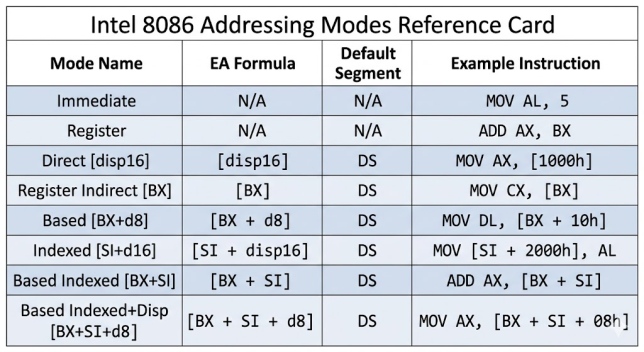
Every memory instruction on the 8086 asks the same question: where is the data? The answer is an Effective Address (EA) — a 16-bit offset computed entirely inside the Execution Unit before the Bus Interface Unit ever touches the address bus. How that EA is computed is what defines the addressing mode. The choice you make directly affects instruction size, clock cycles, and code readability, so picking the right mode for each situation matters.
The EU computes the 16-bit EA using one of the formulas below, then passes it to the BIU along with a segment register identifier. The BIU applies the formula: Physical Address = (Segment × 16) + EA and drives the result onto the 20-bit address bus.
| Mode | EA Formula | Default Segment | EA Clocks |
|---|---|---|---|
| Immediate | (no memory) | — | — |
| Register | (no memory) | — | — |
| Direct | [disp16] | DS | 6 |
| Register Indirect | [BX] / [SI] / [DI] | DS | 5 |
| Register Indirect | [BP] | SS | 5 |
| Based / Indexed | [BX+disp] / [SI+disp] | DS | 9 |
| Based | [BP+disp] | SS | 9 |
| Based Indexed (fast) | [BX+SI] / [BP+DI] | DS / SS | 7 |
| Based Indexed (slow) | [BX+DI] / [BP+SI] | DS / SS | 8 |
| Based Idx + Disp (fast) | [BX+SI+disp] / [BP+DI+disp] | DS / SS | 11 |
| Based Idx + Disp (slow) | [BX+DI+disp] / [BP+SI+disp] | DS / SS | 12 |
Segment override adds 2 clock cycles. Word at odd address costs 4 extra cycles (two bus cycles).
Immediate and Register Modes
Both require no memory access and complete in minimum clock cycles:
; Immediate: operand is encoded in the instruction bytes
MOV AX, 1234h       ; AX = 1234h
ADD CX, 100         ; small constants use sign-extended 1-byte form
CMP AL, 0Dh         ; compare with carriage return

; Register: both operands in registers, no bus cycle needed
MOV AX, BX
ADD CL, DH
XCHG SI, DI
Direct Addressing
EA is a 16-bit constant in the instruction. Used for named global variables — the assembler replaces the label with its numeric offset at assemble time.
.data
    counter DW 0
.code
    MOV AX, [counter]       ; EA = offset of counter in DS
    MOV AX, [0200h]         ; EA = 0200h (literal offset)
    INC WORD PTR [counter]
Register Indirect
EA is the current value of one register. Only four registers are valid: BX, SI, DI (default DS), and BP (default SS). Attempting [AX], [CX], [DX], or [SP] is an assembler error — a hardware constraint, not a convention.
MOV AX, [BX]        ; AX = word at DS:BX
MOV AL, [SI]        ; AL = byte at DS:SI
MOV DX, [DI]        ; DX = word at DS:DI
MOV CX, [BP]        ; CX = word at SS:BP  ← note SS, not DS!

; Walk an array
MOV BX, OFFSET array
MOV CX, 10
XOR AX, AX
next:
    ADD AX, [BX]
    ADD BX, 2
    LOOP next
XLAT — Table Lookup Addressing
XLAT (also written XLATB) is the only 8086 instruction that forms an effective address from two 8-bit values: EA = BX + AL. It replaces AL with the byte at DS:[BX + AL] in a single clock cycle. No other instruction can use AL as an address component — XLAT is a unique hardware shortcut for single-byte lookup tables of up to 256 entries.
; Hex digit table: convert 0-15 into ASCII hex character
.data
    hex_table DB '0123456789ABCDEF'  ; 16 bytes at known offset

.code
    MOV BX, OFFSET hex_table   ; BX = base of table
    MOV AL, 0Fh                ; AL = index (0-15)
    XLAT                       ; AL = hex_table[AL] = 'F' (46h)

    ; Seven-segment display decoder: 8 segments for digits 0-9
    MOV BX, OFFSET seg_table
    MOV AL, digit              ; AL = digit 0-9
    XLAT                       ; AL = segment pattern for that digit
XLAT executes in 11 clock cycles — slower than a direct MOV AL, [BX+SI] (8+EA = 13 clocks with [BX+SI]), but it uses only one register for both base and index. Its real value is readability and compactness: one instruction, one byte of opcode (D7h), no need to load SI or DI. The table must fit within a single 256-byte segment window reachable from DS:BX.
Based and Indexed Addressing
Based mode adds a displacement to BX or BP. Indexed mode adds a displacement to SI or DI. Both are ideal for accessing a fixed field within a struct (displacement = field offset, register = struct pointer).
; Struct with fields: age at offset 0, score at offset 2
AGE   EQU 0
SCORE EQU 2
    MOV BX, OFFSET player
    MOV AX, [BX + AGE]      ; player.age
    MOV DX, [BX + SCORE]    ; player.score
    INC WORD PTR [BX + SCORE]

; Stack frame access (BP defaults to SS — no override needed)
my_proc PROC
    PUSH BP
    MOV  BP, SP
    MOV  AX, [BP + 4]       ; first parameter
    MOV  BX, [BP + 6]       ; second parameter
    MOV  [BP - 2], AX       ; local variable 1
    POP  BP
    RET
my_proc ENDP
Based Indexed Addressing
EA = Base (BX/BP) + Index (SI/DI). The four valid pairs — [BX+SI], [BX+DI], [BP+SI], [BP+DI] — are not equally fast. An asymmetry in the 8086 address adder makes [BX+SI] and [BP+DI] 1 clock faster than [BX+DI] and [BP+SI]. Prefer the fast pairs in tight loops.
| Form | EA | Segment | EA clocks |
|---|---|---|---|
| [BX+SI] | BX + SI | DS | 7 |
| [BP+DI] | BP + DI | SS | 7 |
| [BX+DI] | BX + DI | DS | 8 |
| [BP+SI] | BP + SI | SS | 8 |
| [BX+SI+disp] | BX+SI+disp | DS | 11 |
| [BP+DI+disp] | BP+DI+disp | SS | 11 |
| [BX+DI+disp] | BX+DI+disp | DS | 12 |
| [BP+SI+disp] | BP+SI+disp | SS | 12 |
; 2D array access: matrix[row][col] where each row = COLS words
ROWS EQU 4
COLS EQU 8
.data
    matrix DW ROWS * COLS DUP(0)
.code
    ; Access matrix[2][3]: AX = row, DX = col
    MOV AX, 2
    MOV CX, COLS * 2        ; bytes per row
    MUL CX                  ; AX = row offset in bytes
    MOV BX, AX              ; BX = row base
    MOV SI, 6               ; col 3 * 2 bytes
MOV AX, matrix[BX+SI] ; fetch element (fast pair!)Only BX, SI, DI, and BP can appear inside square brackets — using [AX], [CX], [DX], or [SP] is a hardware encoding error. Among the two-register combinations, [BX+SI] and [BP+DI] are 1 clock faster than [BX+DI] and [BP+SI] due to an asymmetry in the 8086’s address adder. In a tight inner loop this difference adds up — always prefer the fast pairs for 2D array and matrix traversal.
String Instructions
String instructions are a specialised form of register-indirect addressing that automatically adjusts the index registers after each operation. They always use DS:SI as source and ES:DI as destination. The Direction Flag (DF) controls whether SI/DI increment (CLD) or decrement (STD) after each step. REP, REPE, and REPNE prefixes repeat the instruction using CX as a counter.
| Instruction | Source | Destination | Adjusts | Use With |
|---|---|---|---|---|
| MOVSB/W | DS:SI | ES:DI | SI, DI | REP (bulk copy) |
| CMPSB/W | DS:SI | ES:DI | SI, DI | REPE (find mismatch) |
| SCASB/W | AL/AX | ES:DI | DI | REPNE (search buffer) |
| LODSB/W | DS:SI | AL / AX | SI | No REP (loop manually) |
| STOSB/W | AL / AX | ES:DI | DI | REP (fill buffer) |
Byte ops: SI/DI ±1. Word ops: SI/DI ±2. REPE: repeat while CX≠0 AND ZF=1. REPNE: repeat while CX≠0 AND ZF=0. DF=0 (CLD) increments; DF=1 (STD) decrements.
If a previous ISR left DF=1, your REP MOVSB will silently copy memory backward. This corrupts data before your source buffer with no error. Call CLD at the start of any function that uses string instructions.
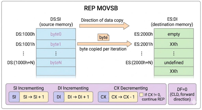
; — REP MOVSB: copy 200 bytes —————————————————————————————————
MOV AX, DS
MOV ES, AX              ; same segment for source and destination
LEA SI, source
LEA DI, dest
MOV CX, 200
CLD                     ; forward direction (SI++, DI++)
REP MOVSB               ; copy 200 bytes

; REP MOVSW: same result, half the iterations (faster!)
MOV CX, 100             ; word count
REP MOVSW

; — REPNE SCASB: find '$' terminator (strchr-style) ——————————————
MOV AX, DS
MOV ES, AX
LEA DI, my_string
MOV AL, '$'             ; character to find
MOV CX, 256
CLD
REPNE SCASB             ; scan: stop when AL == ES:DI or CX=0
JNZ not_found
DEC DI                  ; DI was incremented past the match; back up

; — REPE CMPSB: compare two strings ———————————————————————————
LEA SI, str1
LEA DI, str2
MOV CX, 20
CLD
REPE CMPSB              ; stop at first mismatch or CX=0
JE  strings_equal       ; ZF=1: all matched
; ZF=0: mismatch at SI-1 / DI-1

; — REP STOSB: zero-fill a 256-byte buffer ——————————————————————
MOV AX, DS
MOV ES, AX
LEA DI, buffer
XOR AL, AL
MOV CX, 256
CLD
REP STOSB
Segment Override Prefixes
Any data memory access can override its default segment using a one-byte prefix: CS: (2Eh), DS: (3Eh), ES: (26h), SS: (36h). The prefix adds 2 clock cycles. The destination in string instructions (DI → ES) cannot be overridden; the source (SI → DS) can.
MOV AX, [BX]        ; default: DS
MOV AX, ES:[BX]     ; override: ES (+2 clock cycles)
MOV AX, CS:[BX]     ; override: CS (read from code segment)
MOV AX, SS:[BX]     ; override: SS
Read Next & Related Articles
- Read next: ⑥ Flag Register — REPE/REPNE use ZF; string direction uses DF — both explained here
- ⑦ Stack Operations — [BP+offset] is based addressing defaulting to SS
- ① Memory Segmentation — the physical address formula behind each EA calculation
- ③ Data Directives — DB, DW, DD, DUP, EQU
- The Complete 8086 Register Reference — which registers are valid in EA and which are not
- 8086 Flag Register — REPE/REPNE use ZF; string direction uses DF
- 8086 Stack Operations — [BP+offset] is based addressing defaulting to SS
- 8086 Data Directives: DB, DW, DD, DQ, DT, DUP, EQU
FAQs
Q: Why can’t I use [AX], [CX], or [DX] as indirect addresses?
This is a hardware encoding constraint. The ModRM byte — the opcode byte that specifies which registers are used in a memory reference — has no encoding for AX, CX, DX, or SP as base/index registers. The valid set is exactly {BX, BP, SI, DI}.
Q: Why is [BX+SI] faster than [BX+DI]?
The 8086 address calculation unit has two adders. BX and BP feed one adder; SI and DI feed the other. Combining from the same adder group ([BX+DI] or [BP+SI]) requires an extra adder stage, costing 1 additional clock cycle. [BX+SI] and [BP+DI] cross-pair the two adders and finish in one step.
Q: What happens if I forget CLD before a string instruction?
If DF was left as 1 (STD) by a previous routine, your REP MOVSB or REP STOSB will run backward — decrementing SI and DI instead of incrementing them. This silently corrupts memory before or at the source buffer. Always call CLD at the start of any function that uses string instructions.