
In 1978, Intel released the 8086 and changed computing permanently. It was the chip that powered the original IBM PC, seeded the x86 architecture that still runs every Windows and Linux machine today, and introduced the pipelined fetch-execute model that every modern CPU descends from. If you are studying microprocessors — for an exam, for embedded systems work, or out of curiosity about how computers actually work at the hardware level — the 8086 is where the story starts. This post covers the processor’s origin and key features first, then moves into the memory segmentation mechanism that underlies every single memory access it ever makes.
Introduction to the Intel 8086
A Brief History
Intel’s microprocessor story begins with the 4-bit 4004 (1971), moves through the 8-bit 8008 (1972) and the landmark 8080 (1974), and reaches the 8085 (1976) — a refined 8-bit chip that was popular but fundamentally limited: 8-bit registers, 64 KB address space, no hardware multiply, no pipeline. By the mid-1970s minicomputers were running 16-bit and 32-bit code, and it was clear that 8-bit CPUs had hit a ceiling.
Intel began the 8086 project in 1976 under lead designer Stephen Morse, with the explicit goal of delivering a true 16-bit architecture that remained software-compatible with the 8085 at the assembly level. The chip was fabricated on a 3-micron HMOS process, packed 29,000 transistors into a 40-pin DIP package, and was released in June 1978 at an initial clock speed of 5 MHz. Two years later, IBM chose the cheaper 8-pin-narrower sibling — the 8088, which kept the 8086’s internal 16-bit architecture but used an 8-bit external data bus — for the original IBM PC 5150 (August 1981). That decision made the x86 architecture the dominant platform for personal computing, a position it still holds.
| Processor | Year | Data Bus | Address Bus | Max RAM | Transistors |
|---|---|---|---|---|---|
| Intel 8080 | 1974 | 8-bit | 16-bit | 64 KB | 6,000 |
| Intel 8085 | 1976 | 8-bit | 16-bit | 64 KB | 6,500 |
| Intel 8086 | 1978 | 16-bit | 20-bit | 1 MB | 29,000 |
| Intel 8088 | 1979 | 8-bit external | 20-bit | 1 MB | 29,000 |
| Intel 80286 | 1982 | 16-bit | 24-bit | 16 MB | 134,000 |
Key Architectural Features
Six features define what the 8086 is and why it was a genuine leap over the 8085:
| Feature | Detail | Significance |
|---|---|---|
| 16-bit registers | AX, BX, CX, DX, SI, DI, SP, BP (all 16-bit); splittable into 8-bit halves | Native 16-bit arithmetic, larger data ranges, backward compatibility through 8-bit sub-registers |
| 20-bit address bus | AD0–AD19 (multiplexed); reaches 2²⁰ = 1,048,576 bytes | 16× the address space of the 8085; segment:offset bridged the 16-bit register gap |
| Two-stage pipeline | BIU fetches instructions into a 6-byte queue while EU executes | Fetch and execute overlap; fetch latency mostly hidden — the key innovation |
| Memory segmentation | Four 16-bit segment registers (CS, DS, SS, ES) define 64 KB windows | Lets 16-bit offsets address a 1 MB space; enables separate code, data, and stack regions |
| Hardware multiply/divide | MUL, IMUL, DIV, IDIV instructions; 8×8 → 16 and 16×16 → 32 bit | The 8085 had no hardware multiply — software substitutes were 10–100× slower |
| String instructions | MOVS, CMPS, SCAS, LODS, STOS with REP prefix | Block memory operations in a single instruction loop; critical for OS and I/O performance |
Applications
The 8086 and its descendants appeared in four broad categories of systems. Personal computers are the most famous — the IBM PC (8088), IBM PC/AT (80286), and the entire DOS era ran on x86 chips. Industrial and embedded control systems used the 8086 for its deterministic timing and rich I/O support: programmable logic controllers, CNC machine controllers, and test instruments from the early 1980s through the mid-1990s commonly used 8086 or 80186 cores. The 80186 in particular was a single-chip version that integrated the CPU, interrupt controller, timer, and DMA controller — widely used in modems, printers, and network equipment. Medical devices and military systems favored the 8086’s predictable real-time behavior and the availability of radiation-hardened versions. The architecture also became the dominant teaching vehicle for university microprocessor courses worldwide — a role it still fills today, because understanding real mode 8086 gives students direct intuition for how modern x86 protected mode, segmentation, and paging evolved from it.
Every x86 processor manufactured today — Intel Core, AMD Ryzen — boots in real mode and executes the same reset vector sequence as the 1978 8086. The instruction encoding, segment register model, and flag register layout you learn here are directly visible in modern 64-bit CPUs. Understanding the 8086 is not archaeology; it is the foundation of the platform that runs the world.
The Physical Address Formula
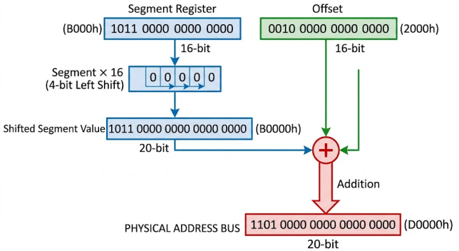
The Intel 8086 is a 16-bit processor — every register holds at most 16 bits, giving a maximum direct offset of 65,535 bytes. Yet the address bus is 20 bits wide, capable of reaching 1,048,576 bytes (1 MB) of memory. Bridging this gap with no extra hardware was a clever piece of engineering: combine a 16-bit segment register with a 16-bit offset inside a dedicated adder, and the result is a 20-bit physical address. That mechanism is memory segmentation, and it underlies every single memory access the 8086 ever makes.
| Segment | Offset | Segment × 16 | Physical Address |
|---|---|---|---|
| CS = 2000h | IP = 0150h | 20000h | 20150h |
| DS = ABCDh | BX = 1234h | ABCD0h | ACF04h |
| SS = 4000h | SP = FFFEh | 40000h | 4FFFEh |
The segment value is always paragraph-aligned (multiple of 16). The offset is a 16-bit unsigned value (0000h–FFFFh).
The Four Segment Registers
The 8086 has four 16-bit segment registers. The BIU automatically selects which one to use for each type of memory access based on a fixed set of hardware rules.
| Register | Name | Default paired with | Primary use | Can override? |
|---|---|---|---|---|
| CS | Code Segment | IP | All instruction fetches | No |
| DS | Data Segment | BX, SI, DI, direct | Most data reads/writes | Yes |
| SS | Stack Segment | SP, BP | Stack operations, stack frame access | Yes |
| ES | Extra Segment | DI (string dest) | String instruction destinations | No (for string dest) |
CS — Code Segment
CS is always used for instruction fetches: physical instruction address = CS×16 + IP. CS cannot be loaded directly with MOV — it only changes through far JMP, far CALL, RETF, INT n, or IRET.
; Near JMP — only IP changes
JMP near_label

; Far JMP — both CS and IP change
JMP FAR PTR 3000h:0100h    ; CS = 3000h, IP = 0100h
DS — Data Segment
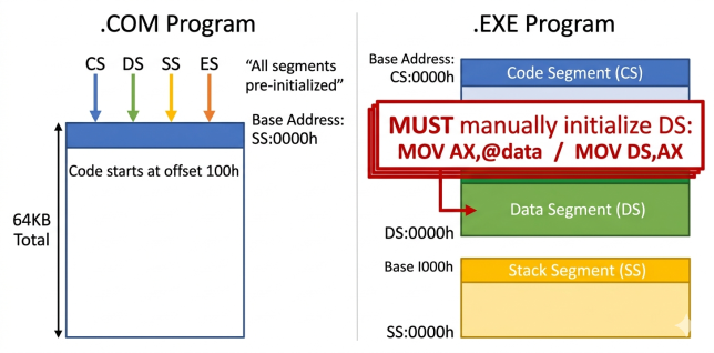
DS is the default for all data memory operands. In .EXE programs, DOS does NOT initialize DS to the program’s data segment — you must do it manually at the start of main.
; Required at start of every .EXE program:
MOV AX, @data     ; @data = paragraph address of .data segment
MOV DS, AX        ; cannot load segment register from immediate

MOV AX, [BX]      ; reads from (DS * 16) + BX
MOV CX, [1234h]   ; reads from (DS * 16) + 1234h
SS — Stack Segment
SS:SP is the hardware stack pointer. Every PUSH, POP, CALL, and RET automatically uses SS. BP also defaults to SS when used in a memory operand — [BP+4] accesses SS segment without any override prefix needed. For full stack mechanics see 8086 Stack Operations.
ES — Extra Segment
ES is the mandatory destination segment for string instructions. MOVSB reads from DS:SI and writes to ES:DI — the ES for the destination cannot be overridden. In single-segment programs, set ES = DS before using string instructions.
MOV AX, @data
MOV DS, AX
MOV ES, AX        ; ES = DS (required for string operations in same segment)
LEA SI, source
LEA DI, dest
MOV CX, 50
CLD
REP MOVSB         ; DS:SI → ES:DI
Default Segment Selection Rules
| Memory access type | Default segment | Overridable? |
|---|---|---|
| Instruction fetch | CS | No |
| Stack: PUSH, POP, CALL, RET, SP-relative | SS | No |
| BP as base register (e.g. [BP+4]) | SS | Yes |
| BX, SI, DI as base or index | DS | Yes |
| Direct address (e.g. [1234h]) | DS | Yes |
| String source (SI) | DS | Yes |
| String destination (DI) | ES | No |
Segment Override Prefixes
Any overridable data access can switch its segment using a one-byte prefix. Cost: 2 extra clock cycles per instruction.
MOV AX, [BX]      ; default: DS
MOV AX, ES:[BX]   ; override to ES (prefix byte 26h)
MOV AX, CS:[BX]   ; override to CS (prefix byte 2Eh)
MOV AX, SS:[BX]   ; override to SS (prefix byte 36h)
Overlapping Segments
Because the physical address is just a shift plus an addition, multiple segment:offset pairs can point to the same physical byte. This is not a bug — it is a deliberate consequence of the design, and experienced programmers used it intentionally.
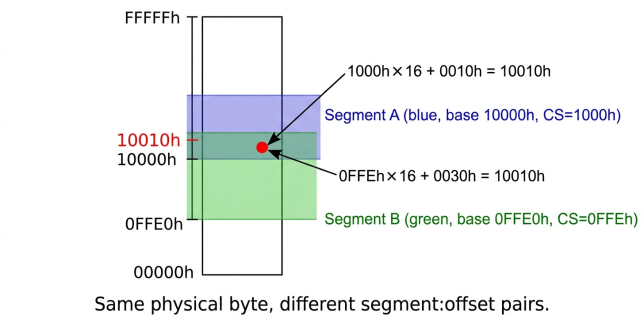
Segment aliasing is a deliberate feature, not a bug. .COM programs intentionally set CS=DS=SS=ES to the same value, letting all four segment registers share a single 64 KB flat workspace without any override prefixes.
The 64 KB Limit and Address Wrap-Around
A segment spans at most 64 KB — offsets 0000h through FFFFh. If an offset increments past FFFFh, it wraps to 0000h within the same segment, not to the next segment. On the original 8086, if the resulting physical address exceeds FFFFFh, it wraps back to 00000h (the A20 line is not driven). The IBM PC AT added the A20 gate to make this wrap-around controllable for compatibility.
.COM vs .EXE Programs
| .COM Program | .EXE Program |
|---|---|
| CS = DS = SS = ES = PSP paragraph IP starts at 0100h (after PSP) No DS initialization needed Max size: 64 KB total |
CS:IP = entry point (from EXE header) SS:SP = stack segment top DS, ES = PSP — must init DS manually! Max size: 64 KB per segment |
Every .EXE program must start with MOV AX, @data then MOV DS, AX before accessing any [variable]. DOS loads DS pointing to the PSP, not your data segment. Forgetting this produces silent garbage reads with no assembler warning.
Segment Initialization Rules
Segment registers cannot be loaded from immediate values — there is no encoding for MOV DS, 1000h. You must route through a general-purpose register.
; Always via a GPR:
MOV AX, 1000h
MOV DS, AX

; Load segment + offset together from a far pointer in memory:
LDS SI, [far_ptr]     ; DS:SI = far pointer at [far_ptr]
LES DI, [ptr2]        ; ES:DI = far pointer at [ptr2]

; Copy segment register to another:
MOV AX, DS
MOV ES, AX            ; ES = DS

; INVALID — assembler error:
; MOV DS, 1000h        ; no encoding for immediate-to-segment
Protected Mode: How Segmentation Changes on the 80286
Everything covered so far describes real mode — the mode the 8086 always runs in, and the default mode of all 80286+ processors at power-on. In real mode a segment register holds a raw paragraph address and the formula is simply (segment × 16) + offset. Protected mode, introduced with the 80286, replaces that simple shift-and-add with a full hardware memory protection system. The segment register no longer holds an address — it holds a selector: an index into a table of descriptors that the OS controls.
Real Mode vs Protected Mode at a Glance
| Feature | Real Mode (8086 / 80286 default) | Protected Mode (80286+) |
|---|---|---|
| Segment register meaning | Raw paragraph address (×16) | 13-bit index into GDT or LDT |
| Address space | 1 MB (20-bit) | 16 MB on 80286 (24-bit); 4 GB on 80386+ (32-bit) |
| Memory protection | None — any code can access any address | Hardware-enforced via privilege rings and descriptor limits |
| Interrupt table | IVT at 00000h–003FFh (4-byte far pointers) | IDT anywhere in memory (8-byte gate descriptors) |
| Entering the mode | Default at boot | Set PE bit in MSW (80286) or CR0 (80386) |
| Returning to real mode | Always in real mode | 80286: requires hardware reset. 80386+: clear PE bit in CR0. |
Selectors and Descriptors
In protected mode the 16-bit segment register is reinterpreted as a selector: bits 15–3 are a 13-bit index (0–8191), bit 2 is the Table Indicator (0 = GDT, 1 = LDT), and bits 1–0 are the Requested Privilege Level (RPL, 0–3). The selector is an index into a table of 8-byte descriptors, each of which records the segment’s true base address, its byte limit, and access rights.
| Field | Size | Meaning |
|---|---|---|
| Base | 24 bits | Physical start address of the segment (byte-granular, not paragraph) |
| Limit | 16 bits | Size minus 1 in bytes; CPU raises a General Protection Fault on any access beyond this |
| DPL | 2 bits | Descriptor Privilege Level (0 = most privileged / kernel; 3 = least / user) |
| Type | 4 bits | Code / data / stack / system; readable, writable, executable flags |
| P | 1 bit | Present bit: 0 triggers Not Present fault (used by OS for demand paging) |
GDT, LDT, and Privilege Rings
The Global Descriptor Table (GDT) is system-wide and holds descriptors for OS code, OS data, and any segment all tasks can share. Its base address and limit are stored in the GDTR register, loaded with the LGDT instruction. The Local Descriptor Table (LDT) is per-task and holds descriptors private to one process; its location is stored in the LDTR register. When a selector’s TI bit is 0, the CPU indexes the GDT; when TI=1, it indexes the LDT.
Access between privilege levels is not a free-for-all. The four protection rings (0–3) create a concentric hierarchy: ring 0 is the OS kernel with full hardware access; ring 3 is user application code with no direct I/O or privileged instruction access. Code at a lower privilege level (higher ring number) can only call higher-privilege code through a call gate — a special descriptor that the OS explicitly defines.
Entering Protected Mode
; Minimal protected-mode entry sequence (80286)
CLI                     ; disable interrupts — IDT not set up yet
LGDT [gdt_descriptor]   ; load GDT base + limit into GDTR
LIDT [idt_descriptor]   ; load IDT base + limit into IDTR
MOV  AX, 0001h
LMSW AX                 ; set PE bit (bit 0) in Machine Status Word → enters protected mode
JMP  FAR 08h:pm_entry   ; far jump: selector 08h = first GDT entry (code segment)
pm_entry:
    MOV AX, 10h
    MOV DS, AX
    MOV ES, AX
    MOV SS, AX
Memory Model Directives: .MODEL
Before you write a single line of code or declare a single variable, MASM needs to know how many segments your program will use and whether procedure calls and data pointers are near (16-bit offset only) or far (segment:offset pair). The .MODEL directive at the top of every MASM source file makes this choice.
| Model | Code segments | Data segments | Max code | Max data | Default calls | Default pointers | Output format |
|---|---|---|---|---|---|---|---|
| TINY | 1 (shared) | 1 (shared) | 64 KB total (code+data+stack combined) | Near | Near | .COM only | |
| SMALL | 1 | 1 | 64 KB | 64 KB | Near | Near | .EXE |
| COMPACT | 1 | Multiple | 64 KB | 1 MB | Near | Far | .EXE |
| MEDIUM | Multiple | 1 | 1 MB | 64 KB | Far | Near | .EXE |
| LARGE | Multiple | Multiple | 1 MB | 1 MB | Far | Far | .EXE |
| HUGE | Multiple | Multiple | 1 MB | 1 MB | Far | Far | .EXE |
For all programs on this site, use SMALL — one code segment, one data segment, all near calls and near pointers, maximum simplicity. Choose COMPACT, MEDIUM, or LARGE only when a real project genuinely exceeds 64 KB in code or data.
Read Next & Related Articles
- Read next: ② The Complete 8086 Register Reference — all 14 registers, mandatory roles, FLAGS bit table
- ③ Data Directives: DB, DW, DD, DUP, EQU — how variables map into segments
- ④ BIU/EU Architecture & Pin Diagram — how the BIU’s address adder uses the segment formula every cycle, plus the full 40-pin signal reference
- ⑤ Addressing Modes — which segment register applies to each EA mode
- ⑦ Stack Operations — SS:SP mechanics and BP stack frame access
- Top 60 8086 Viva Questions and Answers (2026) — Sunday-exam-prep companion covering the whole series, each answer linked back to the post it comes from
FAQs
Q: Why are segment registers 16-bit if they produce 20-bit addresses?
Widening the registers to 20-bit would have increased die area and bus complexity significantly. The shift-and-add trick produces a 20-bit base from a 16-bit value at zero silicon cost — a dedicated adder is cheaper than wider registers.
Q: What does @data mean in MASM?
@data is an assembler predefined symbol that resolves to the paragraph address (segment value) of the .data segment at link time. DOS patches this value when it loads the .EXE into whatever physical address it found free in memory.
Q: Is it safe to modify SS at runtime?
Yes, with care. The 8086 delays interrupt recognition for one instruction after a MOV to SS. Always place MOV SS, reg and MOV SP, reg as consecutive instructions so no interrupt can fire between them with a half-configured stack.
Q: Why did Intel choose 40 pins for the 8086 package?
40 pins was the largest standard DIP package in common production at the time. Intel’s engineers deliberately designed the address and data buses to share pins (multiplexing AD0–AD15) so that the 20-bit address bus plus 16-bit data bus plus control signals could all fit within that 40-pin constraint. The ALE signal tells external latches when the address is valid and should be captured, freeing those pins for data on the next clock. The full pin-by-pin breakdown is in the BIU/EU Architecture & Pin Diagram post.
No Comments yet!